Work in progress

Swanky Switch

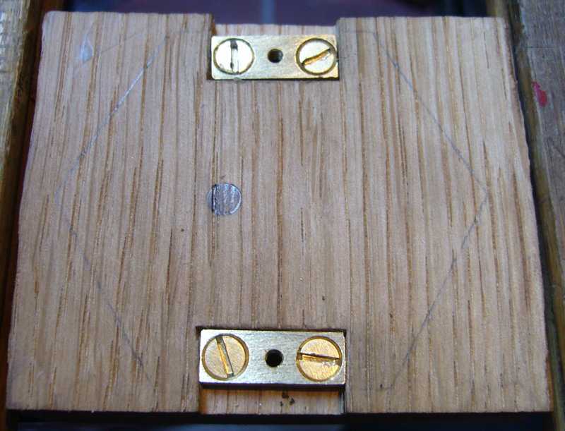
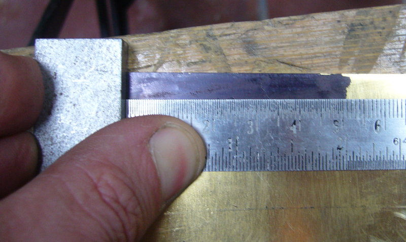
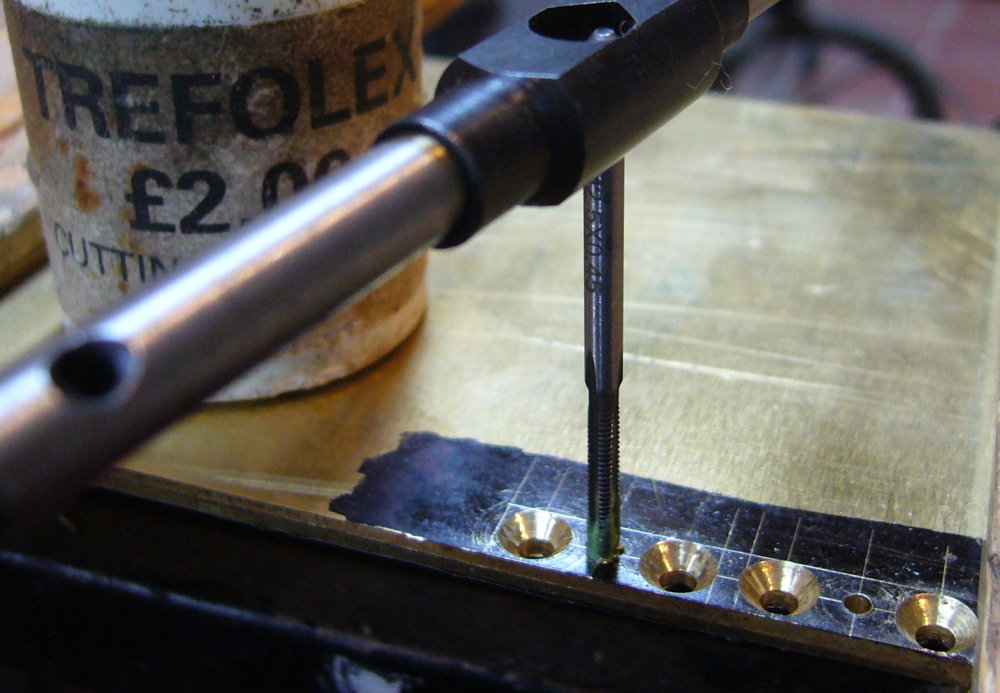
I’ve spent what seems like an inordinate amount of time getting the bellpush switch right. This photo shows my first attempt:

switch1

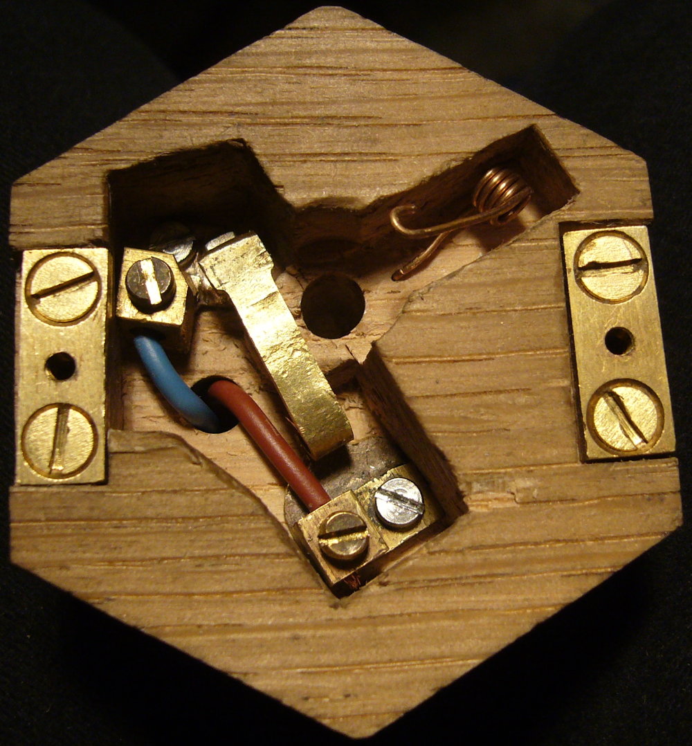
The long contact strip is made from a roughly T shaped strip of 0.7mm brass. It’s bent into a zig-zag at one end to make it more flexible (I also had to file it narrower for the same reason). One of the problems I ran into was I initially didn’t recess the contacts deep enough to ensure the terminal screws can’t press against the underside of the top. The top of the flexible strip is slightly curved so that when the lip of the button pushes down on it, it flexes a little and ‘wipes’ the contacts against each other to (in theory) break through any oxide film that may have developed since the last time it was used. The contacts are made of short sections of flattened 4mm diameter sterling silver rod (for good corrosion resistance), silver-soldered onto the brass parts. The screw terminals are salvaged from a UK 13A mains plug, filed a bit narrower due to the limited space available. I did all the soldering with the Eclipse spirit blowpipe described in an earlier article. They are held down by M2.5 stainless steel machine screws, mated to square S.S. nuts morticed into the back of the box.

When I got to this stage I thought the switch was done. The button action felt nice and the contacts closed when I pressed it. Unfortunately there was a problem, as I discovered when I proudly showed it off to my friend Juliet. She pressed it normally a couple of times and it worked fine, then she tried pressing it really gently. It didn’t work. She tried the same thing a few more times with intermittent results and proclaimed it faulty.

It was a user interface problem: press the button down firmly all the way to the bottom and it worked fine. Press it very gently and it was possible to feel the slight increase in resistance as the contacts began to close and stop pressing too soon. Result: the bell doesn’t sound, and you might not realise if you were outside and the bell was inside. I suppose some people seeing such an ornate bellpush might think that it looks delicate and press the button gently in fear of damaging it (in fact you’ve probably got more chance of breaking your finger than the button). This graph illustrates the problem (figures are estimates):

buttonfeel

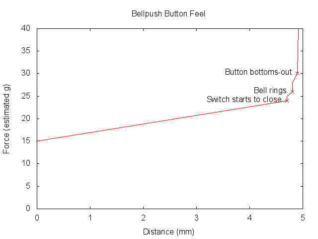
The problem is that first step when the button lip touched the flexible contact strip and the switch began to close. If you were pressing gently enough, it (wrongly) felt like that was the bottom of the button travel when you actually needed to press a tiny bit harder to close the contacts.

I won’t go through the list of ways I tried to solve this problem. I now have quite a collection of discarded springs! What I eventually settled on was a second helical torsion spring attached to the top of the flexible contact that applies gradually increasing pressure to it over the  full length of the button travel. The result is that the switch closes smoothly without any detectable step increase in force, and the contacts are fully closed at about 80% of full travel. If you press the button firmly enough, it bottoms out against the top of the contact strip and wipes the contacts as originally intended.

I also had to remake the first spring with more and bigger coils to weaken it (I could also have used thinner wire but I didn’t have any in stock), because the combination of the two springs made the button force uncomfortably high. I didn’t want to remove the first spring and just use the second one to return the button because it’s set such that the pressure on it is zero at the top of the button travel so as to ensure the contacts release properly, which means the button wouldn’t return to the top as cleanly with that spring alone.

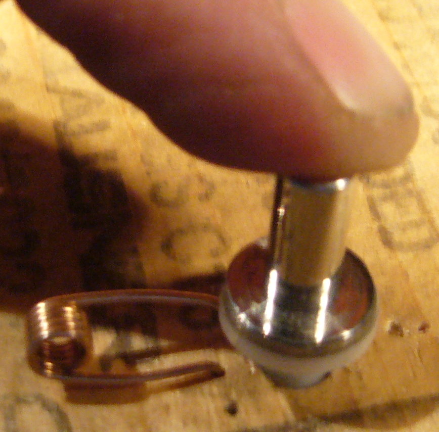
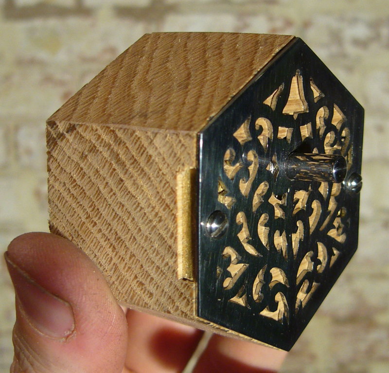
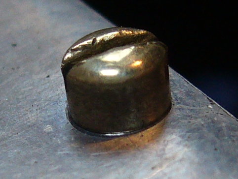
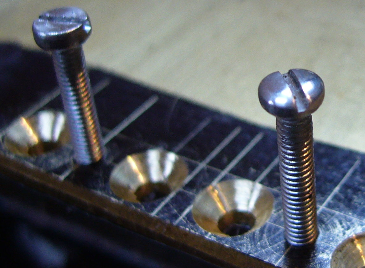
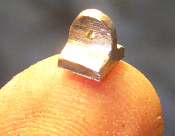
Here’s a cute picture of the little bracket I made to attach the new spring. I filed it from one of the brass 13A plug pins that I got the screw terminals from and silver-soldered it onto the contact end of the flexible strip (that’s a 0.8mm diameter hole):

switch2

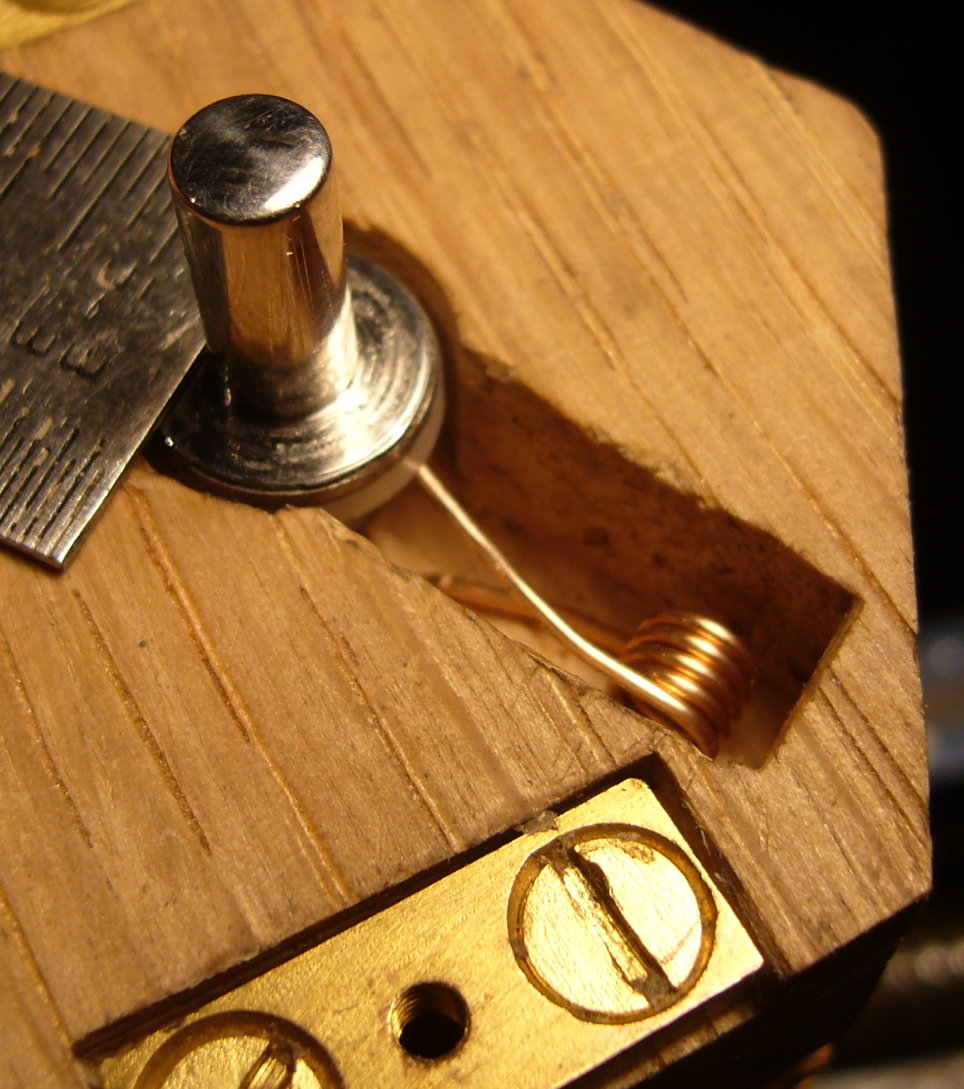
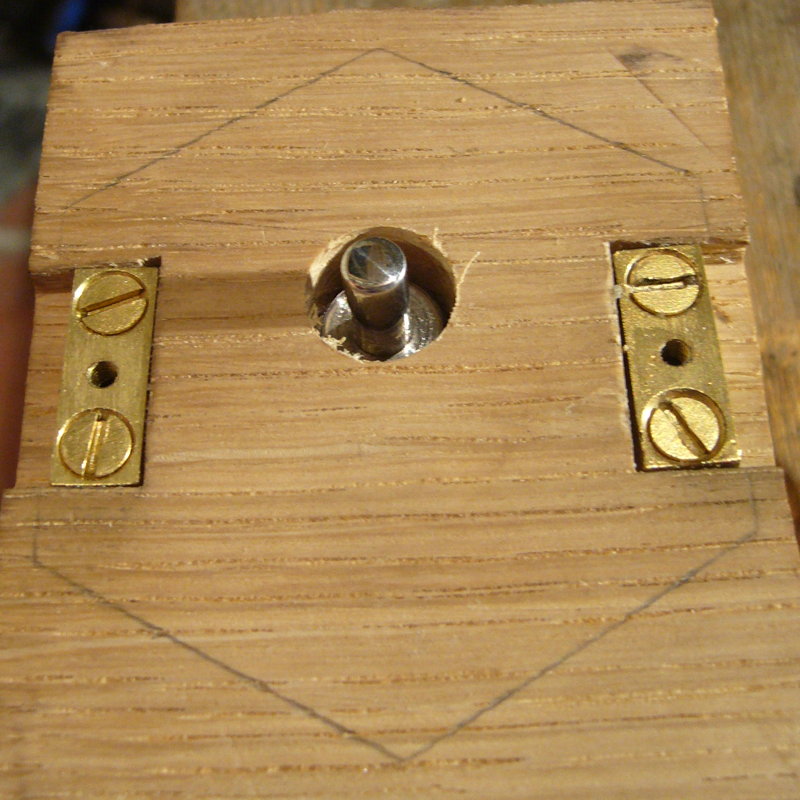
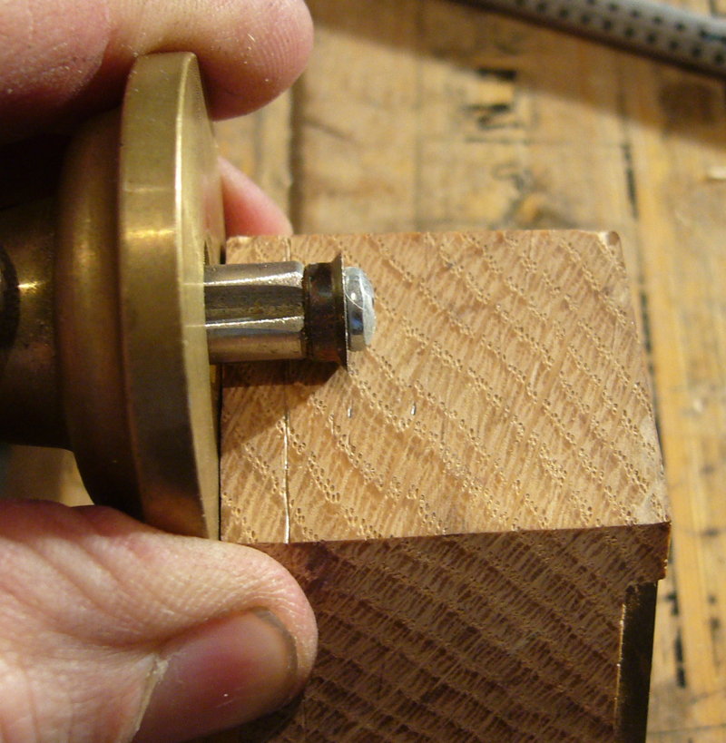
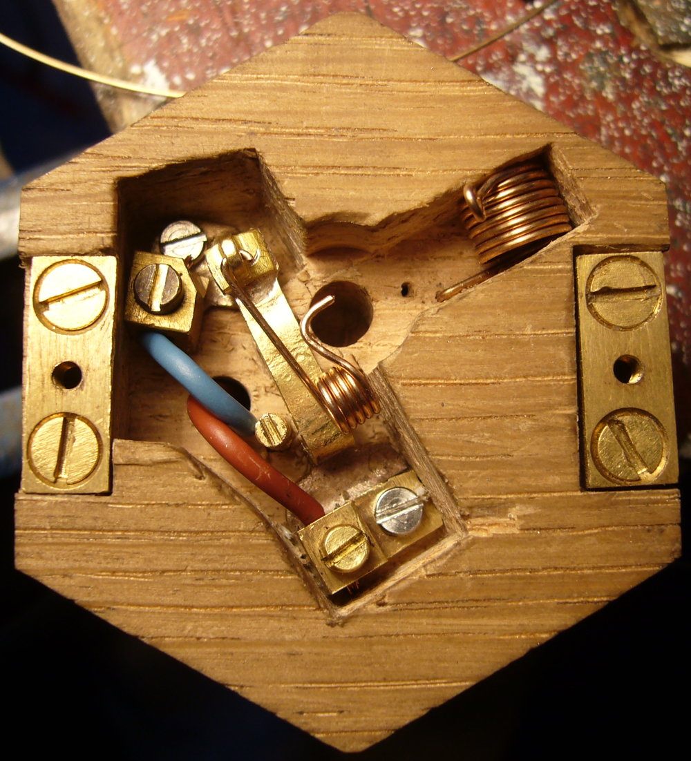
This photo shows the final setup. The brass peg to the left of the flexible contact (a screw with the head filed down) is there to ensure the torsion spring can’t swing to the left and disengage from under the button:

switch3


Now that I had a working bellpush, I wanted to make a little video to show it off. I don’t have an electric bell here and the continuity buzzer in my multimeter doesn’t sound impressive enough, so I hooked it up to something else instead:


Swanky Switch Read More »

Bellpush Spring

Not much progress on the bellpush over the past week because most of my attention has been focussed on another non-concertina-related project. Yesterday was a day off though, so in the evening I managed to stop thinking about the other project for long enough to tackle the problem of the spring that provides the button resistance.

My original plan had been to use a single strip of brass as both the button spring and one of the switch conductors. This turned out to be impractical though because the button has a vertical travel of 5mm and there isn’t enough room inside the box (once you’ve allowed room for mounting screws and electrical screw terminals and things) for a really long spring strip. A short strip probably wouldn’t be able to flex by 5mm without permanently deforming and even if it could, it would likely result in fatigue failure before long. I experimented with folding a brass strip back and forth in a zig zag to increase its effective length, but it looked like it would take up far too much space and probably still wouldn’t work very well.

So the solution I eventually came up with was to separate the two functions. Make a concertina-style spring from coiled phosphor bronze wire with 5mm travel, and a separate brass strip switch that only has to move by 1mm or less at the bottom of the button travel. I haven’t yet made the switch but I have made the spring. It took me four attempts before I developed a shape I was happy with, using a hole in a block of scrap wood as a test rig. It has more turns than a standard concertina spring because of the large amount of movement relative to its length.

bellpush_spring_1

Here it is installed in a recess chiselled into the back box. It’s in a slightly weird location because of where I intend to put the mounting screws and switch contacts:

bellpush_spring_2

I won’t bother posting a photo with the top installed because it doesn’t look any different on the outside! The action feels pretty nice though.


Bellpush Spring Read More »

Bellpush Backbox

I had a day off yesterday, so I managed to make a fair bit of progress on the bellpush. I made the captive nut plates in the morning, then in the afternoon and evening I made the backbox. I decided to make it from a solid chunk of seasoned oak for good weather resistance. My first job after planing the top surface smooth was to spot through the locations of  the two top mounting screws the same size as the clearance holes in the top (i.e. 2.5mm). In order to get them exactly the right distance apart, I drilled the first hole and stuck the shank of a spare drill bit in it while I drilled the second one. For this kind of delicate wood drilling I like to use a hand cranked drill because it gives you a much better feel for the amount of pressure and torque you’re applying to the bit than an electric drill does.

bellpushbackbox1

After drilling the pilot holes, I used a screw inserted through the nut plate to locate it in exactly the right position for chiselling it into the surface of the block.

bellpushbackbox2

It’s trickier than it looks to inset them neatly. The second one is less squiffy than the first! I also must have mis-calculated the width of the nut plates because they were supposed to end up flush with the outside of the box, but there is actually about a 1mm step in. At least both the tapped holes are in exactly the right place, which was the most important thing.bellpushbackbox3


Next I drilled a small diameter pilot hole in the middle of the button hole and used it to guide a sharp flat boring bit to cut a slightly-oversize recess for the large diameter lip of the button (a forstner bit would probably be better but I haven’t got one of those and it worked well enough). The depth of this recess will set how far the button can be pressed in (minus the thickness of the spring).

bellpushbackbox4


Finally I opened up the rest of the pilot hole to slightly over the diameter of the bottom part of the button:

bellpushbackbox5

I had to chamfer the bottom of the button a little to get it to slide smoothly in the hole (should really have thought of that when I was turning the sleeve).bellpushbackbox6

Next I sawed the block to the same shape as the top using my new gent’s saw:

bellpushbackbox7

After a bit of planing to smooth off the saw marks and get it down to the exact size, I thought it looked a bit plain:

bellpushbackbox8

So I scribed three parallel lines near the back of the box: bellpushbackbox9

And carved some fake bellows with my Ashley Iles Vee gouge:bellpushbackbox10


The plastic film behind the fretwork is a tasteful pale green in daylight:

bellpush_preview

But at night it glows in the dark, which looks really cool if I do say so myself! 😉 (Sadly, it only glows this brightly for a few minutes after charging it up by shining an electric light at it.)bellpushbackbox11

Bellpush Backbox Read More »

More Captive Nut Plates


Following my earlier, unsatisfactory, attempt at making a pair of captive nut plates for the bell push by soldering stainless steel nuts onto thin brass sheet, I bought a set of M2.5 taps and a piece of much thicker (3mm) brass sheet for my second try.

I stained the brass with a permanent marker to make the lines show up more clearly, and marked it out using a steel ruler and scriber under magnification:

nutplates1


I also upgraded from a cheap, dull wood-cutting countersink bit to a small good quality (Dormer) HSS three flute metal-cutting countersink. The resulting countersunk holes for the wood screws that will hold the plates to the back box are way smoother, cleaner and more accurate as a result. I tapped the M2.5 holes by hand using Trefolex tapping compound (I bought that small pot at a Model Engineering exhibition about 20 years ago and it’s still half full!).

nutplates2


A brief aside about the heads of the visible machine screws/end bolts that hold the top on. This is what the brass bolt heads look like on my antique Lachenal:

nutplates3


It turns out that head style is called a slotted fillister (I’d not heard that word before I started searching through screw catalogues, and it isn’t in my computer’s spell checking dictionary). I couldn’t find any suitable ready-made M2.5 stainless steel slotted fillister head screws for sale (I much prefer the appearance of slotted heads for this application), so I instead got some cheese-head screws and domed and polished them in the lathe. The next photo shows them before and after modification. Not quite right but I think they look reasonably good.

nutplates4


The final photo shows the two finished nut plates. I’m far happier with how these turned out than I was with my first attempt. The brass wood screws are bigger than necessary, but I happened to have a packet of them sitting around and there is enough room to use them. I don’t think there’s much risk of them pulling out of the oak!

nutplates5

More Captive Nut Plates Read More »