Work in progress

No. 1: Brun Part 7: Reed Pans

The seventh part of the story of how I built my first concertina is about the reed pans; the removable boards that carry the reeds and valves.

One thing I have learned is that the reed pan layout is one of the most difficult and important aspects of designing a new instrument from scratch, and it has to be done in conjunction with the action board layout. It’s no good coming up with a nice logical arrangement of chambers on the reed pans, if it means some of the pad holes end up underneath the keyboard, or the levers have to snake around all over the place to reach the appropriate pads, or you have to use levers that are too short to operate smoothly. Sometimes you have to compromise in one area or another, either in the reed pan (e.g. making reeds smaller because there isn’t room for the ideal size of chambers), or in the action (e.g. making two levers cross over each other or bend sideways).

This being my first instrument and a brand new design, I spent several days at the design stage figuring out a good compromise. When I began the process, I wasn’t even sure how many buttons I was going to end up with (the design brief specified the overall size of the instrument, to include as many buttons as practical in that form factor). The design I came up with looks pretty simple and logical, however in order to reach it, I tried and discarded a number of more complex arrangements. The three main compromises I ended up making were that a few of the levers are shorter than ideal (those buttons feel a bit stiffer than their longer neighbours); six of the chambers are in the centre of the instrument (for reasons I don’t fully understand, they sound a bit less good than chambers on the outside – this is a well-known phenomena in the concertina world); and I was forced to abandon the idea of including an air button.

You might find it interesting to take another look at the photos of Wheatstone’s Duett concertina of the 1850s. My Brun is the same size but with an extra three buttons per side. To achieve that, I went with a similar reed pan arrangement but with a second, smaller pan on each side. Wheatstone’s had one pan with two rows of six chambers; mine has a pan with two rows of five and a second pan with one row of five. Five columns is actually a fairly tight fit in the available width. I tried fitting in six and it was ridiculously tight: I suspect Wheatstone must have used narrower reed frames and smaller diameter pads, which probably had a negative effect on the sound it produced. My actions are a more conventional riveted lever type, and I suspect are probably more comfortable to play.

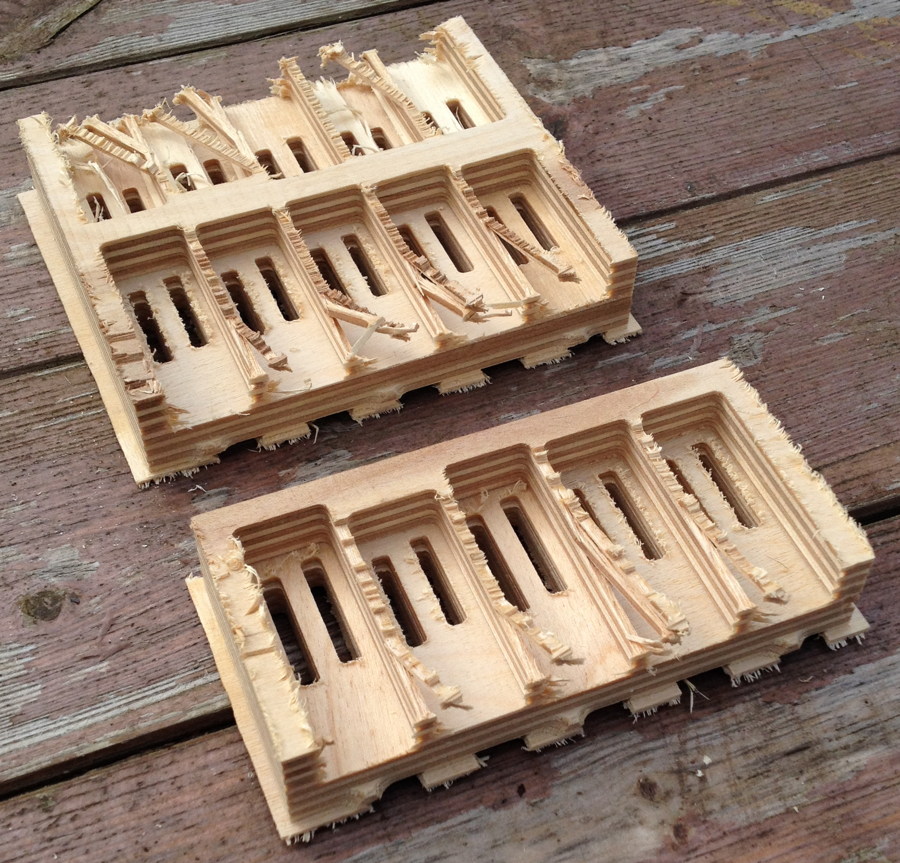
My first idea for making the reed pans was to mill them from thick pieces of birch plywood. This didn’t really work, because the chamber dividing walls were too weak due to the cross-grain layers, causing them to break during the machining process.

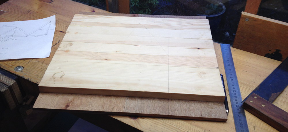
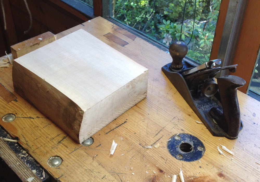
Plan B was to mill them from solid quartersawn sycamore. Using quartersawn wood means it will move and warp less due to changes in humidity level. The little bandsaw I had at the time was just barely powerful enough to rip the slab I had in the thin dimension.

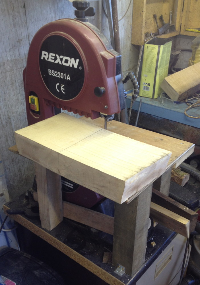
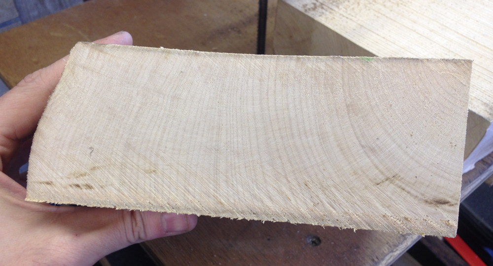
Looking at the end grain, you can see it is reasonably quartersawn towards the bark side of the piece. Because the pans only needed to be a little over 4″ wide, I was able to pick the best section.

Planing one face true.

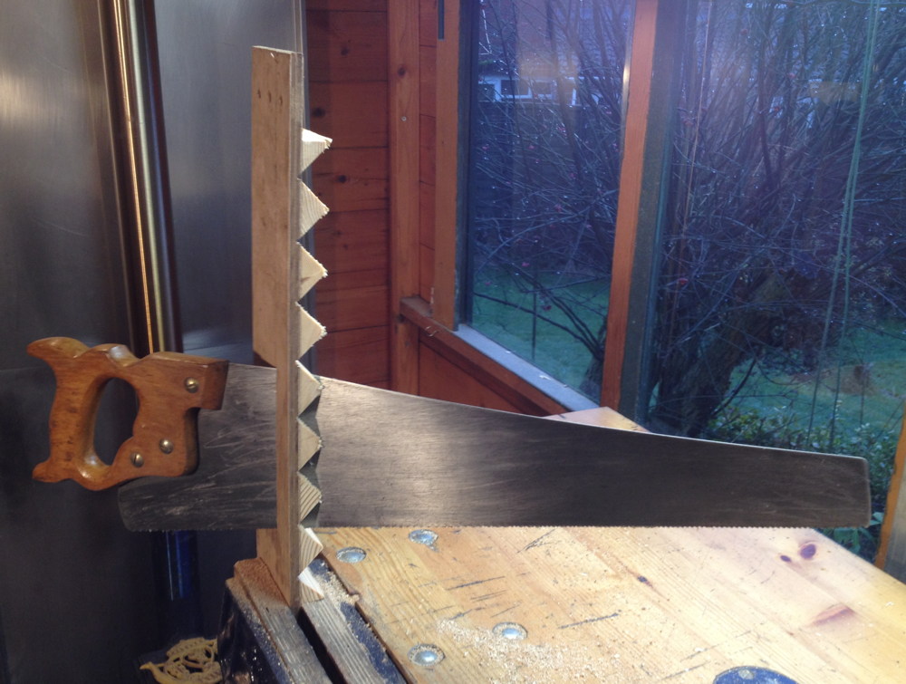
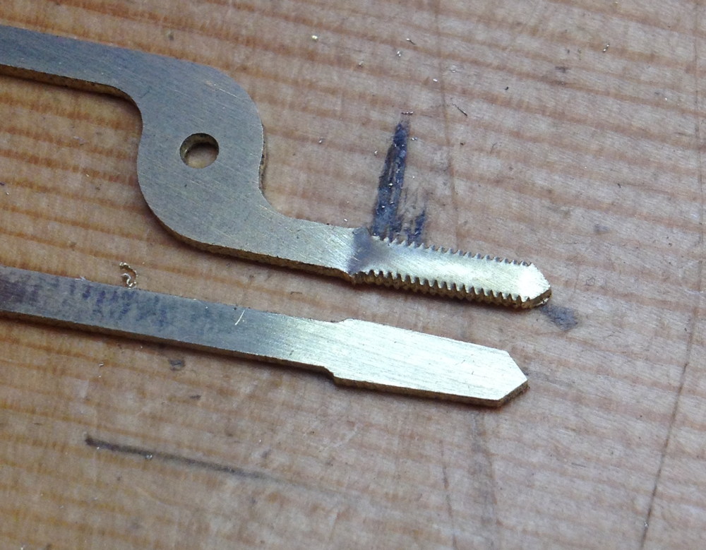
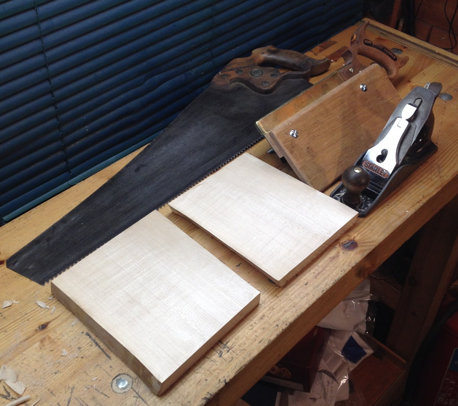
The bandsaw was never going to resaw the full width of the board, so I had to do it by hand. Step 1 was to make a kerfing saw; a special tool that cuts a shallow kerf at a specific distance from the face of the board.

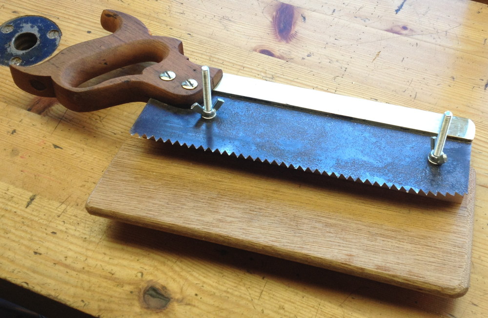
This kerf was then used to help guide the path of an ordinary rip saw.

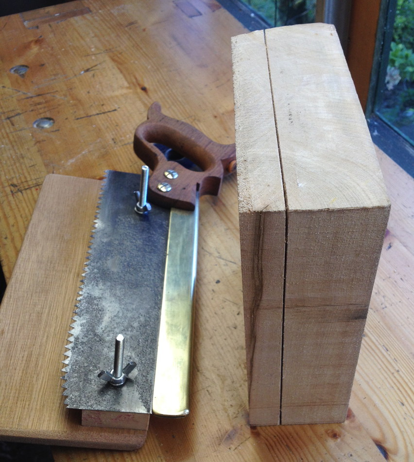
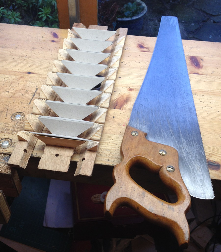
Here are the two roughly sawn reed pan blanks, with the rip saw I used behind them. I’ve since got a bigger rip saw with coarser teeth that would have made the job a bit easier, but it wasn’t too bad really because the boards are so small.

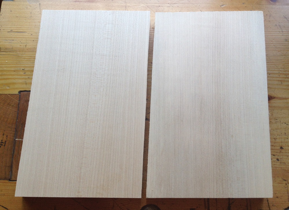
At this point I put the blanks on one side and started recording their weight once a day. Although this slab was supposedly kiln dried before I bought it, it still seemed to have a higher than equilibrium moisture content inside. They lost a few grammes of moisture each over the first few days, and warped a little too. After a couple of weeks they stopped losing weight, so I felt they were probably stable enough to carry on working on them. First I planed one face of each flat and smooth (this face was to become the bottom of the pan) and ripped them narrower, being careful to follow the direction of the grain as closely as possible.

I left the other face alone because I planned to use the milling machine to flatten it, thus getting it very accurately parallel.

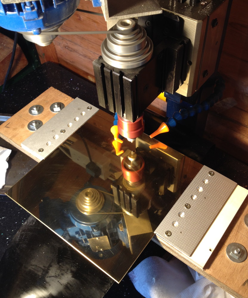
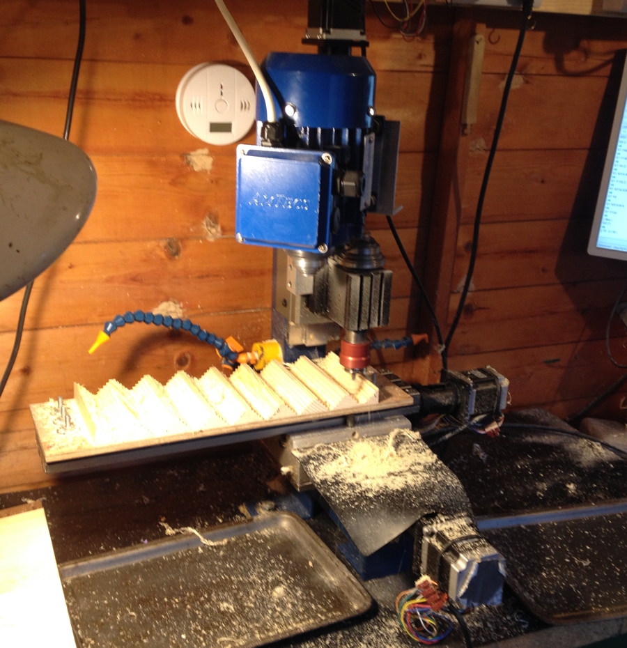
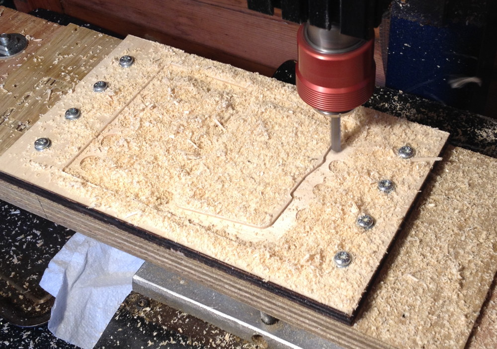
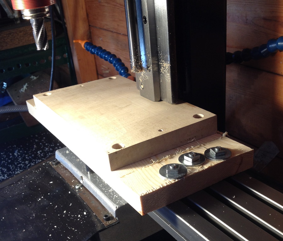
Problem! When I mounted the blank on the milling machine, the back edge fouled on the bottom of the Z axis slide before it was far enough back for the cutter to reach the front of the board.

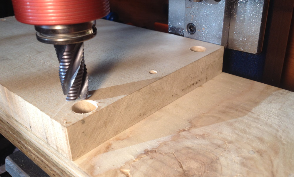
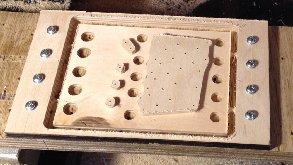
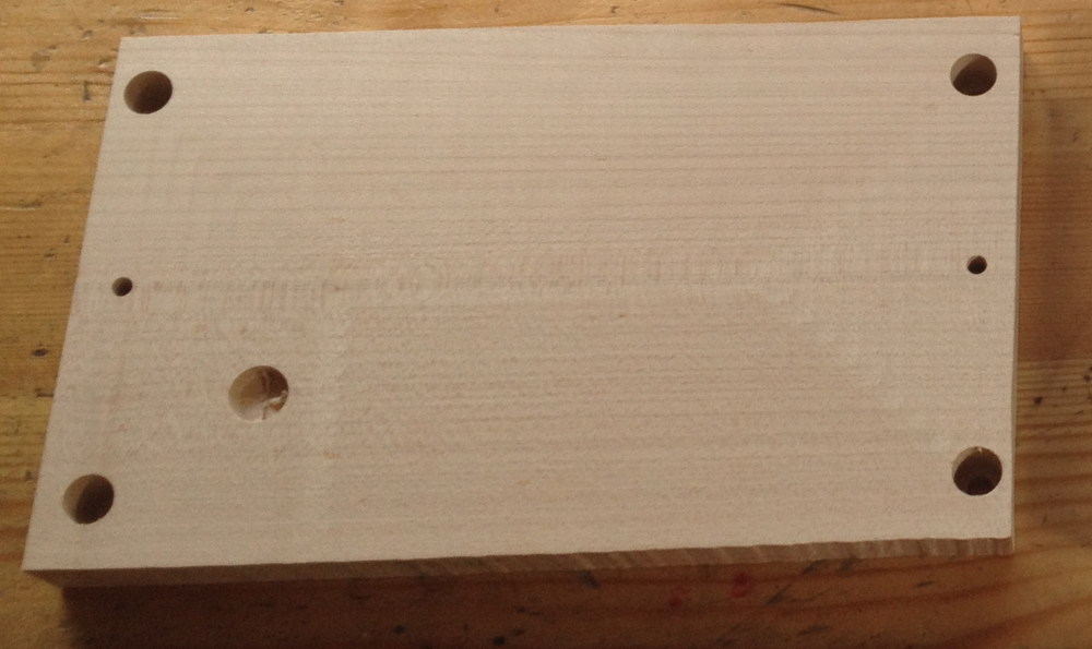
The solution was to make a thinner fixture that (just) allowed the blank to fit under the Z slide. The two small holes in the middle of either end match with registration pins in the spoilboard, thus allowing the blank to be flipped over and still be in the same position, so the bottom reed slots end up in the right place relative to their chambers.

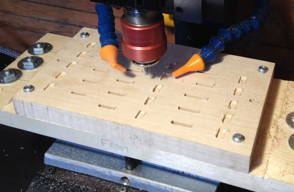
Oops. I did something stupid in zeroing the Z axis and plunged the 1/2″ end mill a few mm deep into the first blank. This could have been a major setback as I didn’t have a spare blank prepared, but luckily I managed to reposition the pan on the blank such that the damage was in an area that was due to be milled out anyway.

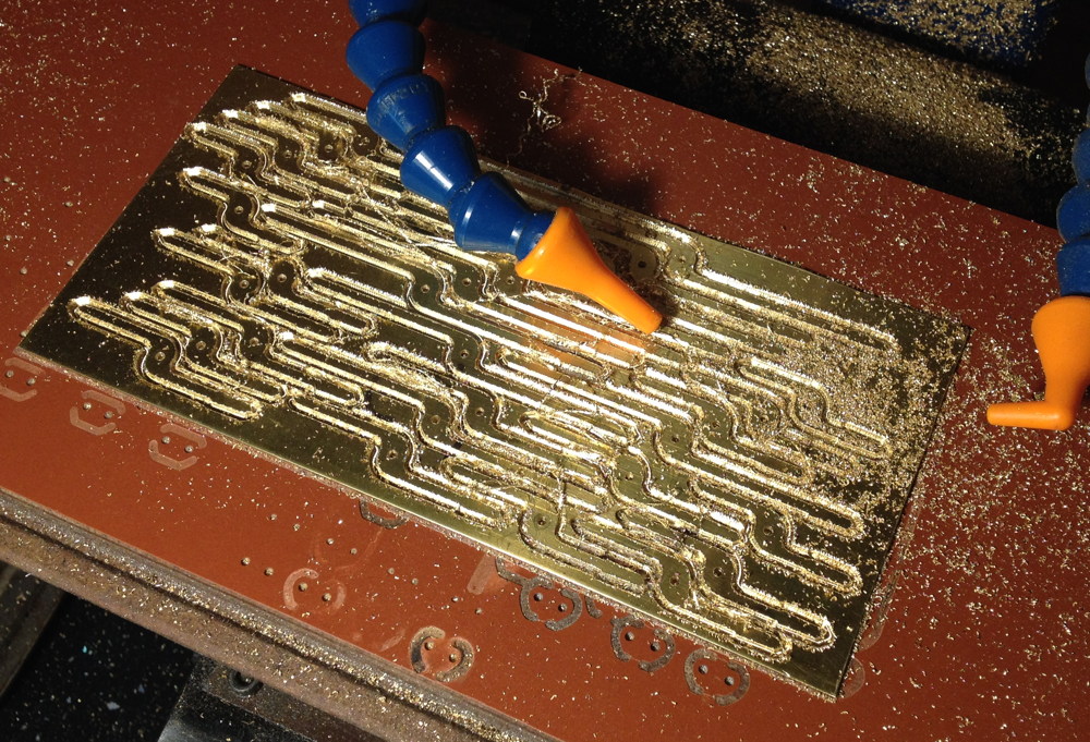
After truing up the top surface, I flipped the piece over and cut the bottom slots. There needed to be little pockets next to each dovetail slot for the dovetail cutter to start in, because the tool isn’t designed to be able to plunge into the work. I cut the wind slots for the bottom reeds at the same time as the dovetail slots, to ensure they are perfectly aligned with each other.

Bottom reed slots cut.

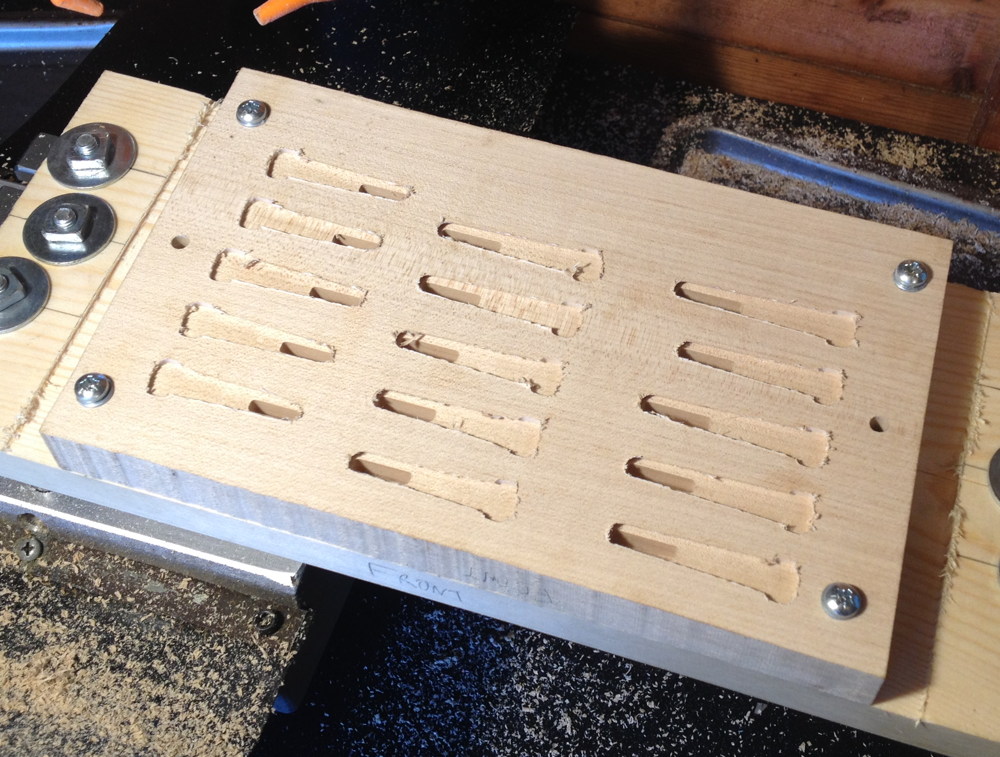
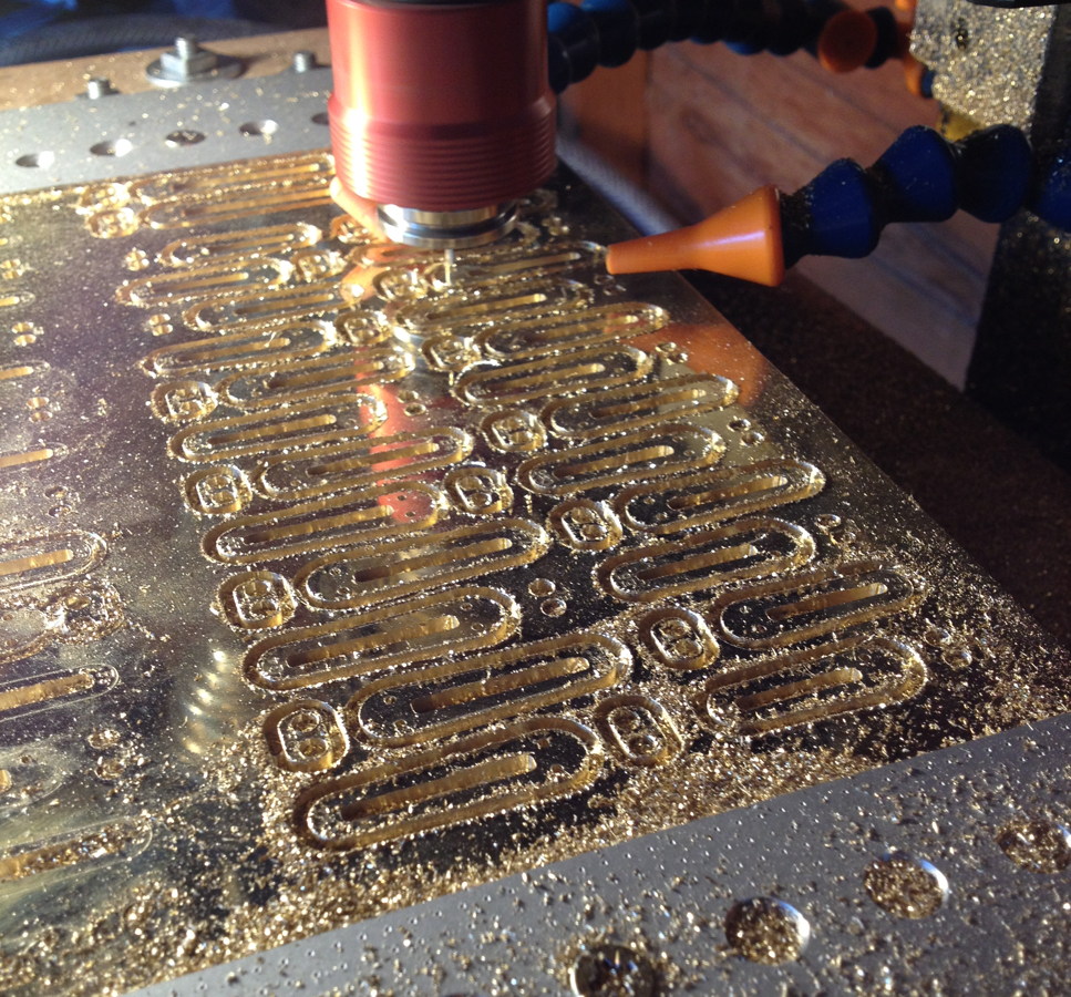
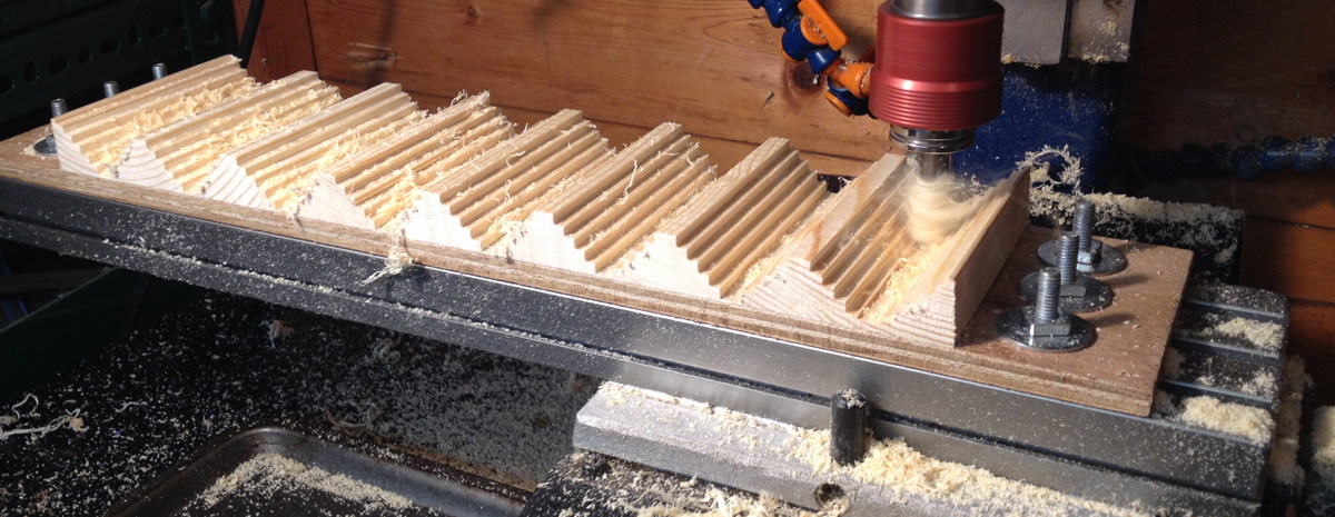
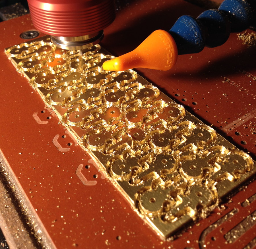
Back to the top again. I cut the outsides of the pans before the chambers, but not all the way through the board, because this reduced the amount of stress on the dividing walls. This picture shows how I managed to position my previous accident inside a region that was due to be removed.

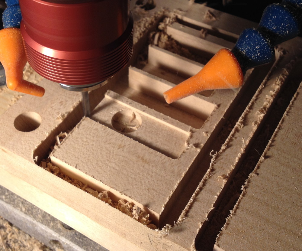
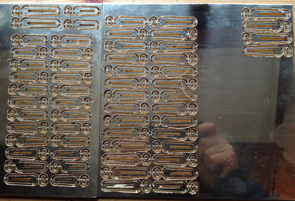
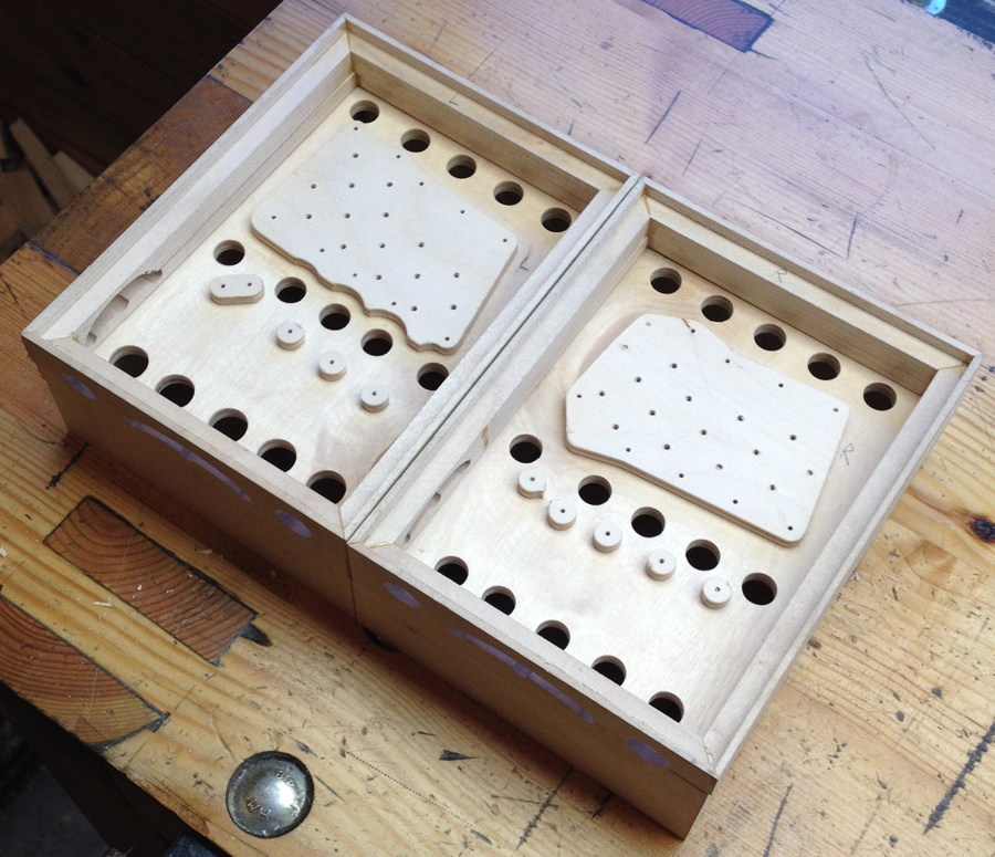
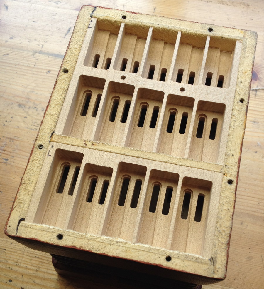
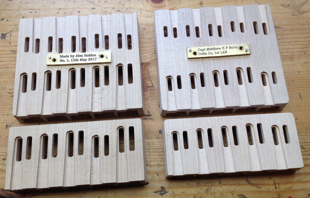
Both reed pans fully routed. The left hand one is off-centre because of the previously mentioned repositioning.

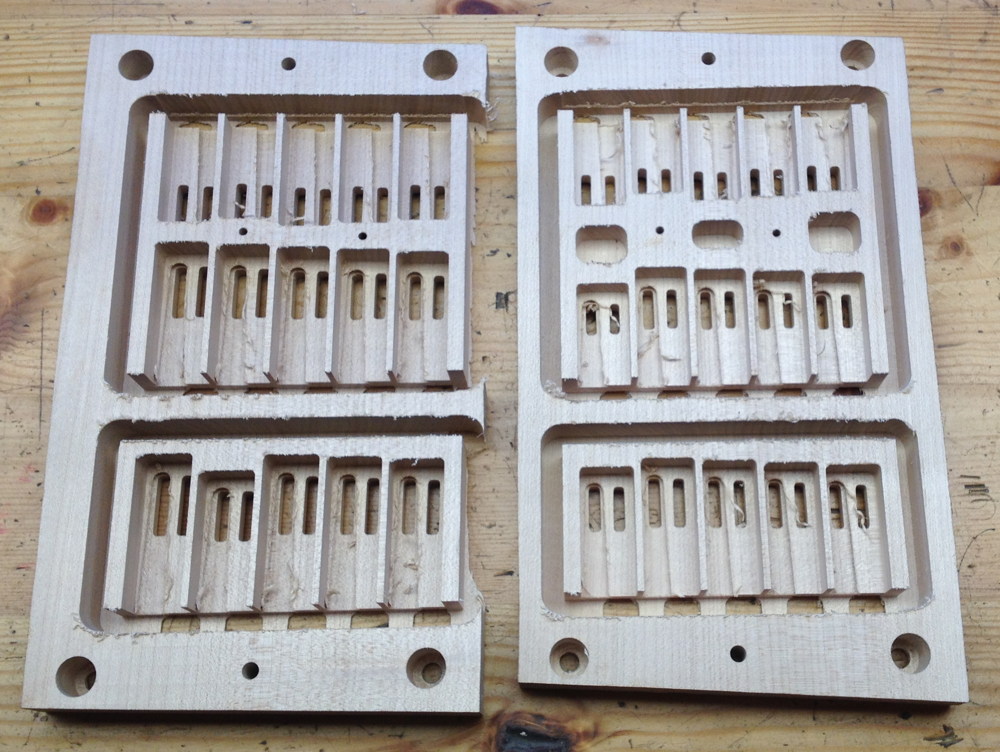
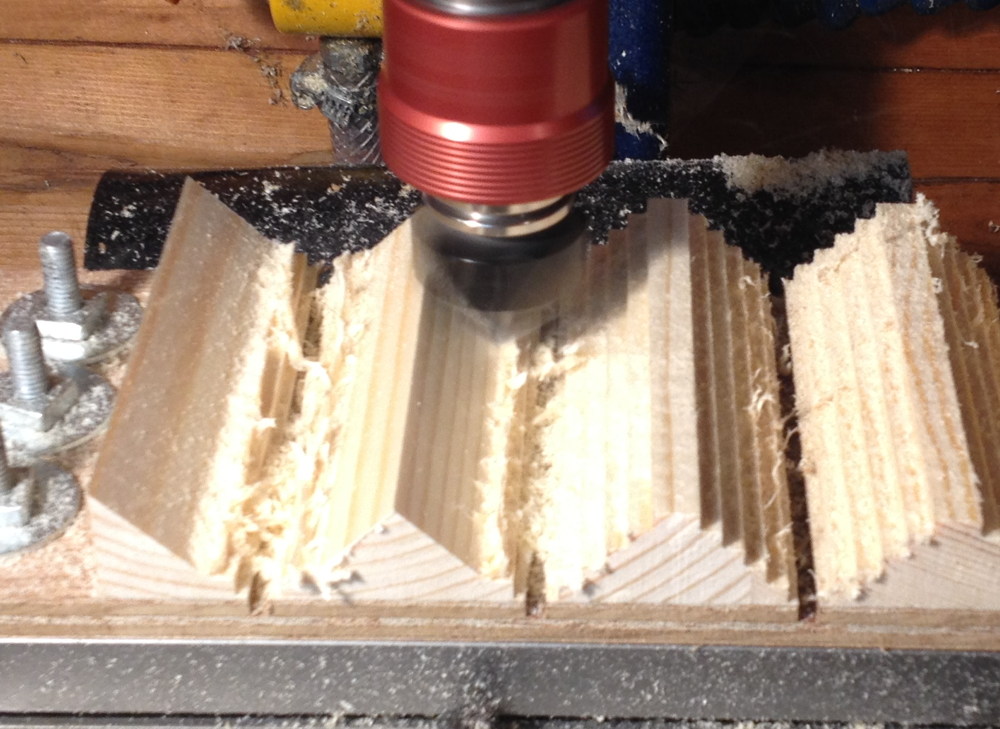
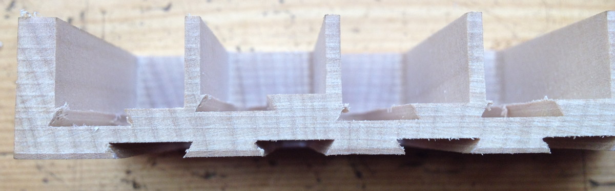
This picture shows a few interesting things. In order to fit the reeds in as tightly as possible, the frames overlap, but not quite enough for a dovetail slot to break into the opposite side’s wind slot. They also undercut the walls slightly, more so at the outside edge (because the frames are tapered). Thirdly, I tried something new here that I haven’t heard of any other maker doing in this way: I made the chambers different depths, based on a ratio of the chamber length. It was common for English concertinas to have sloping pans, where the chambers at one end were deeper than at the other, but that only really works when it’s possible to arrange the pan in such a way that the pitches gradually increase from one end to the other. The way I did it here, it was possible to have a deep chamber right next to a shallow one (the first and second chambers are an octave apart).

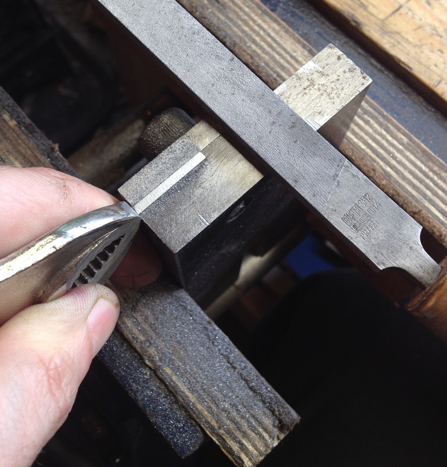
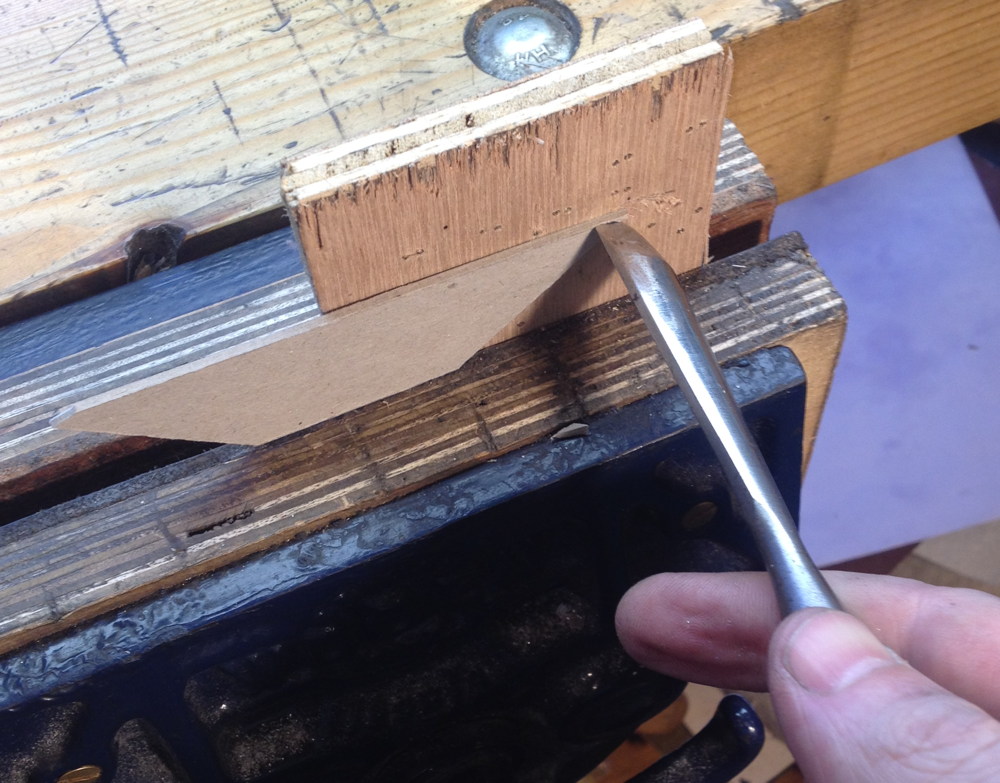
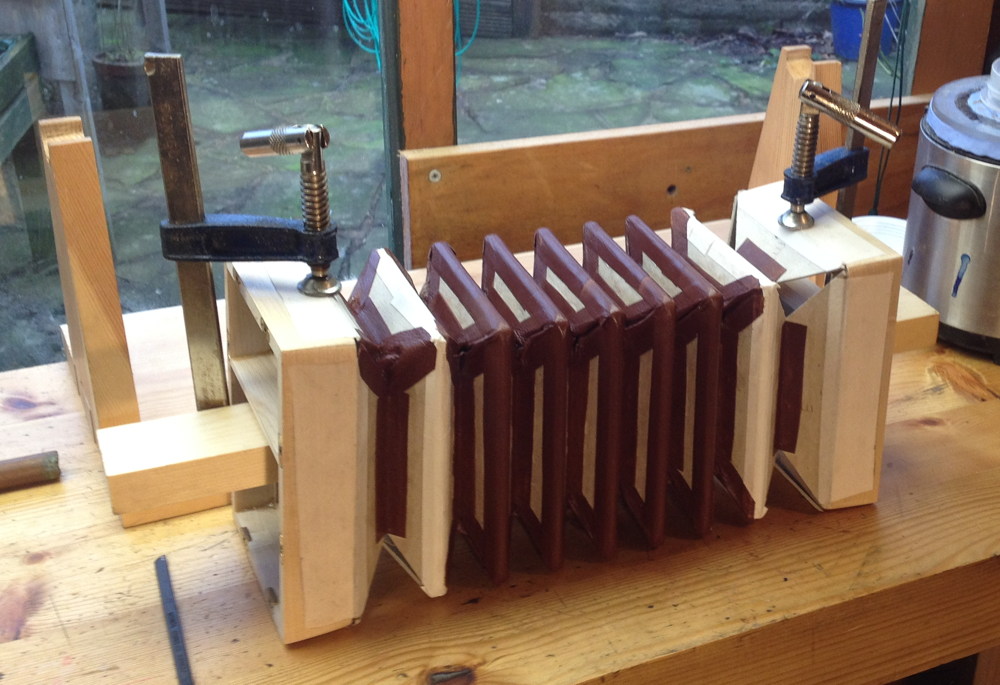
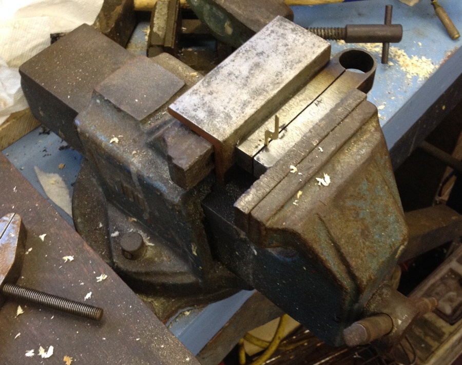
The inner walls of the bellows frame are tapered to get a good seal, so I had to cut a matching taper on the outsides of the reed pans. The side walls I was able to do on the shooting board with a shim to tilt it up.

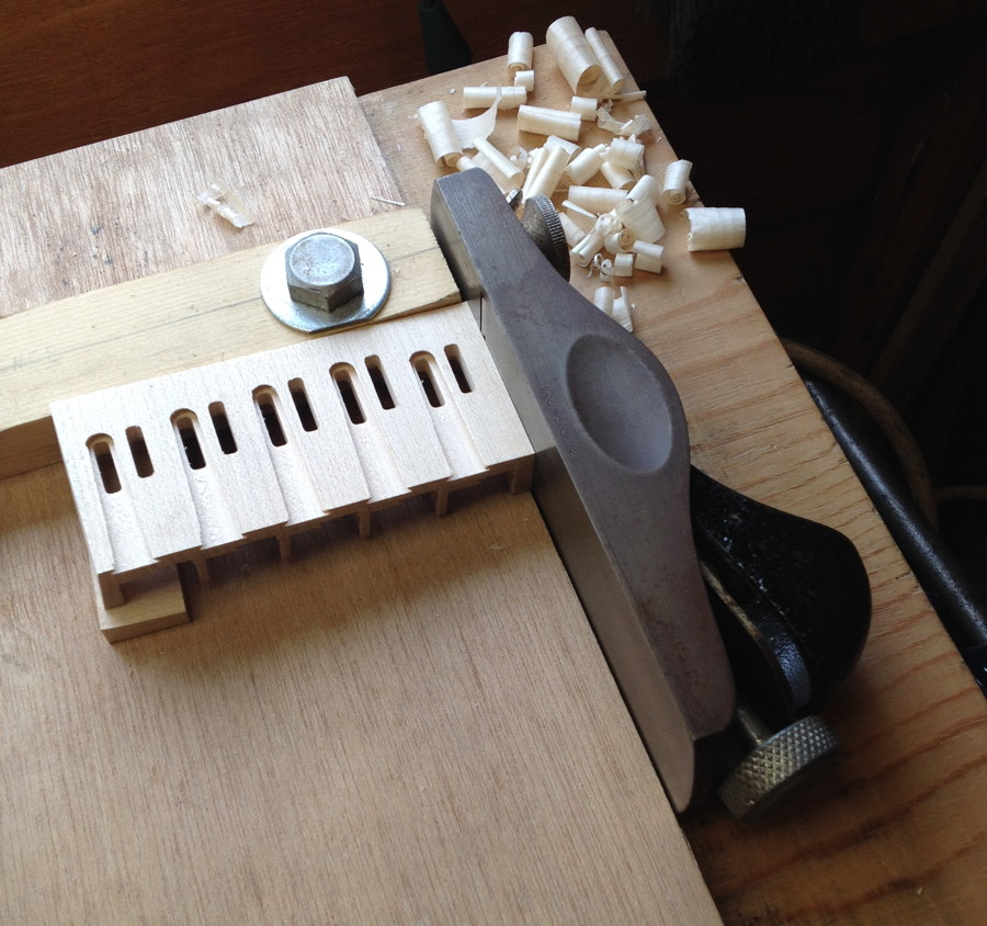
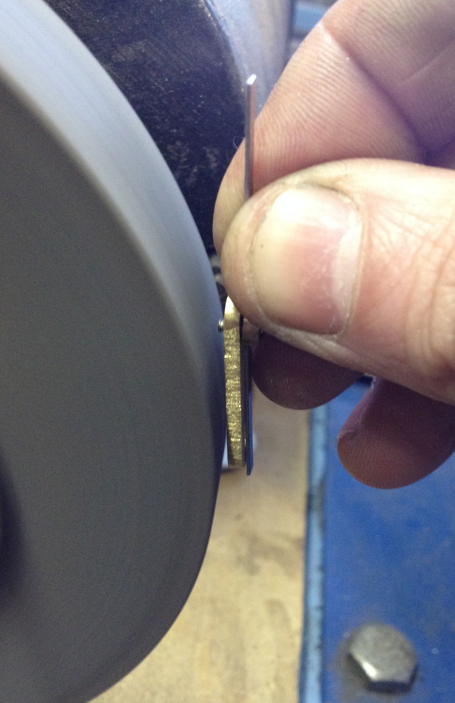
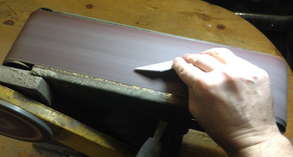
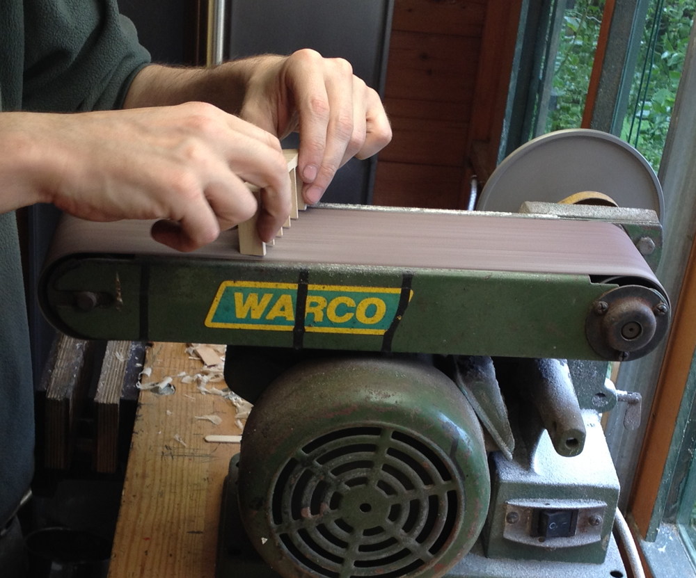
I daren’t try to use the shooting board to plane across the ends of the chamber walls, so I used the linisher for that instead.

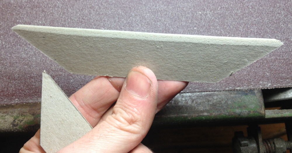
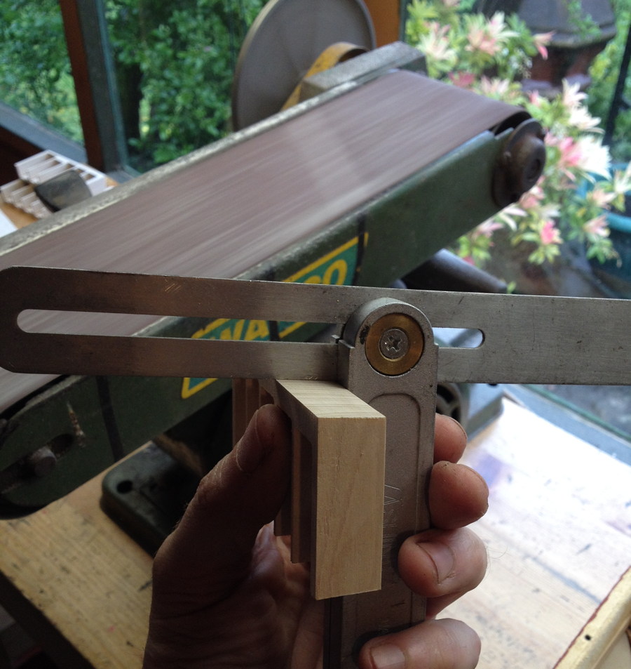
Checking the angle with a bevel gauge.

It took a fair bit of careful work to get a good fit because the earlier problems with the frames not gluing together perfectly square meant the holes the reed pans had to fit into weren’t quite square either. In hindsight it might have been easier if I’d fit the pans to the frames before I put the chamois leather gaskets on the frames, and it definitely would have been much easier to do it before attaching the bellows to the frames.

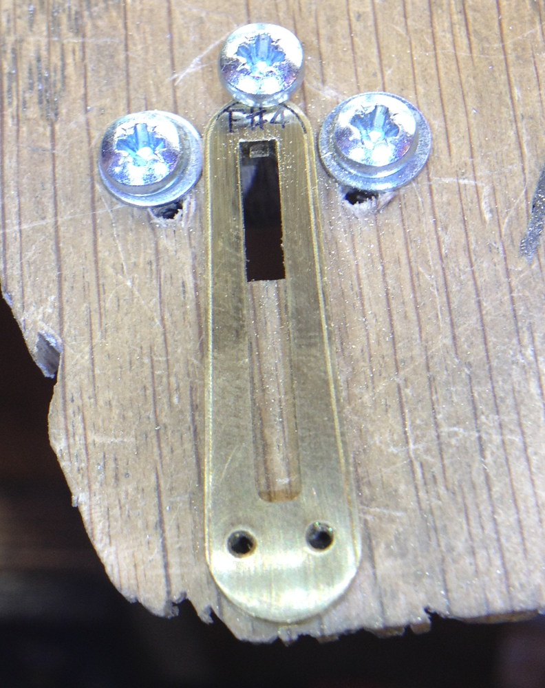
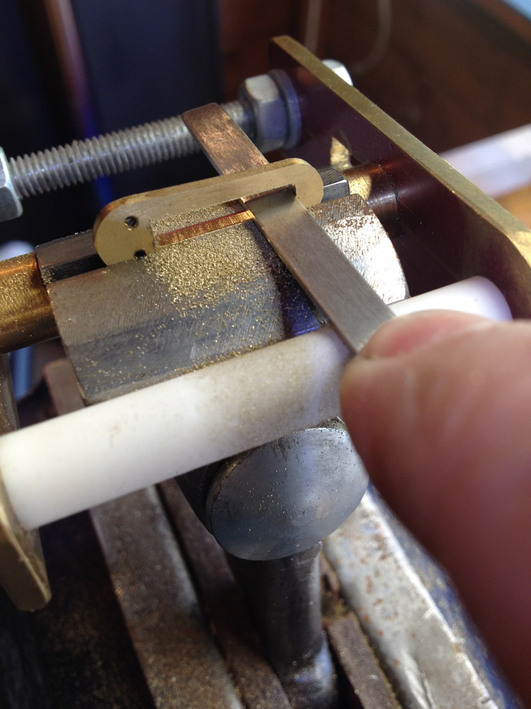
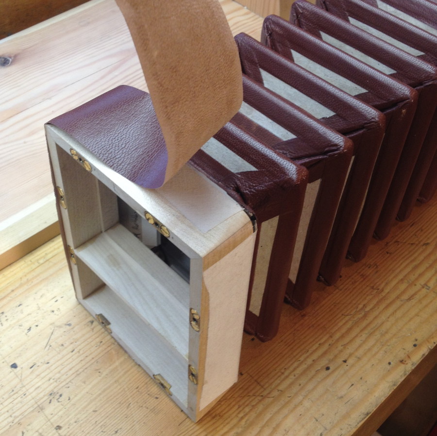
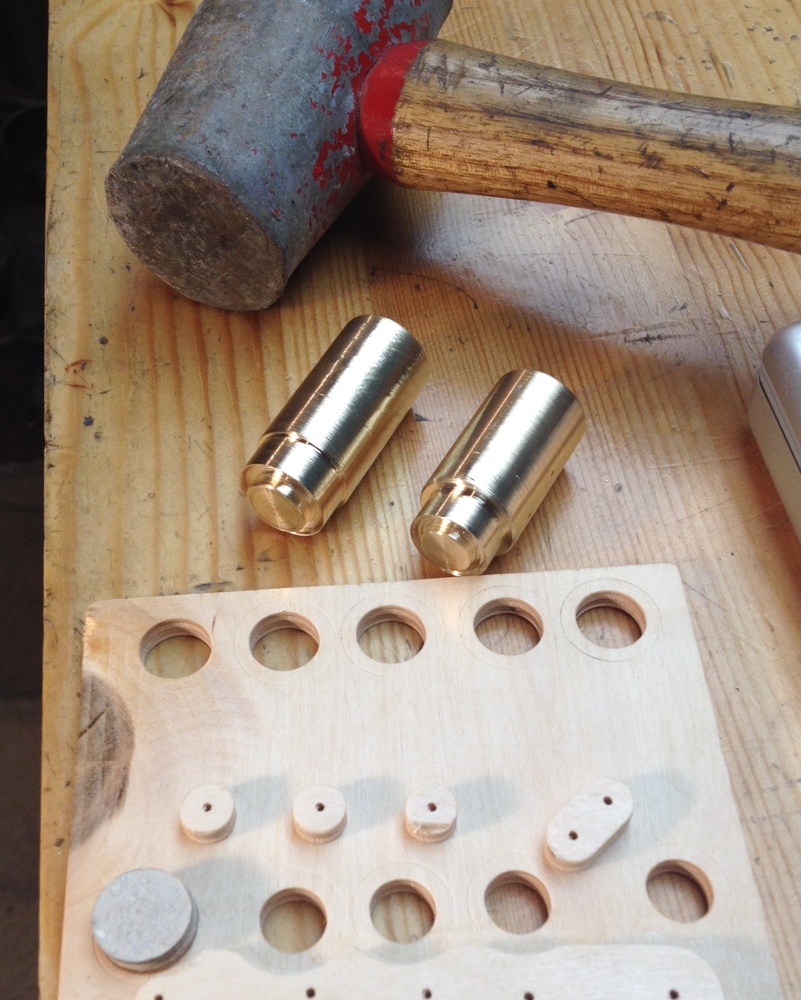
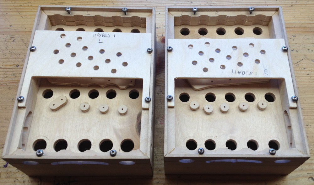
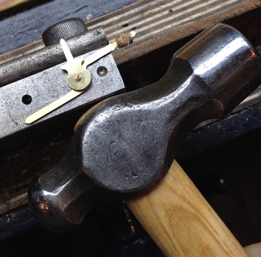
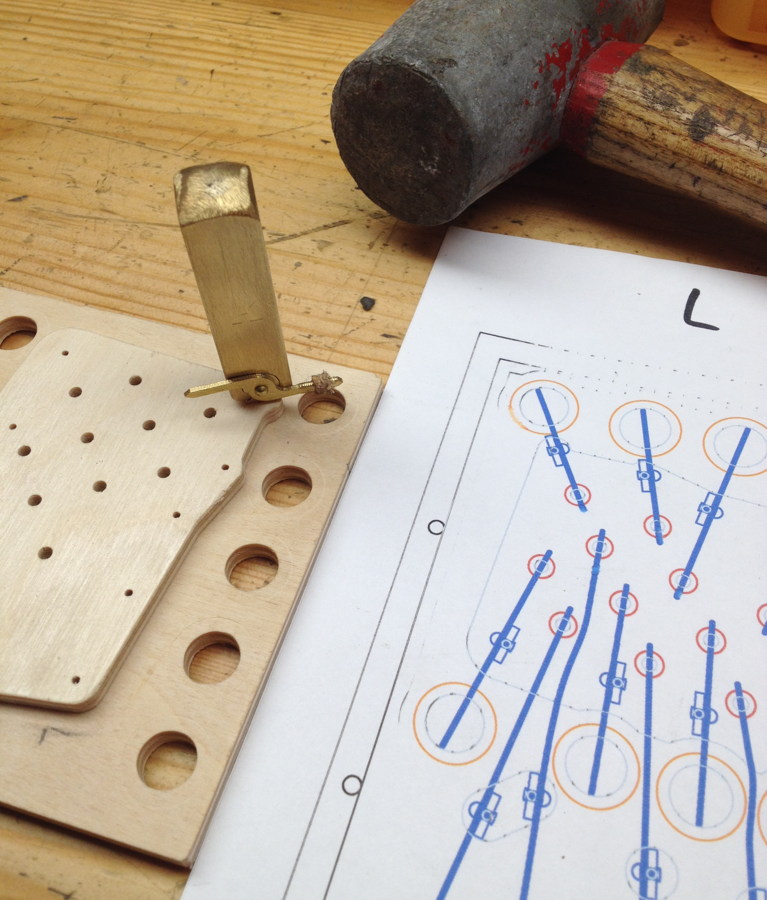
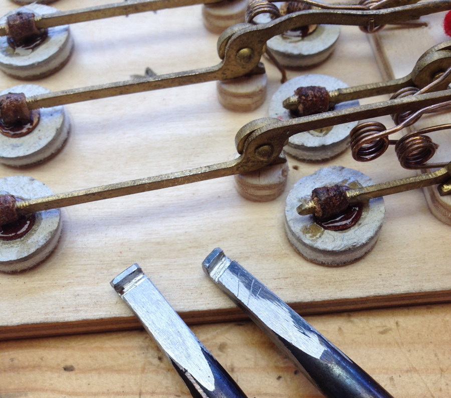
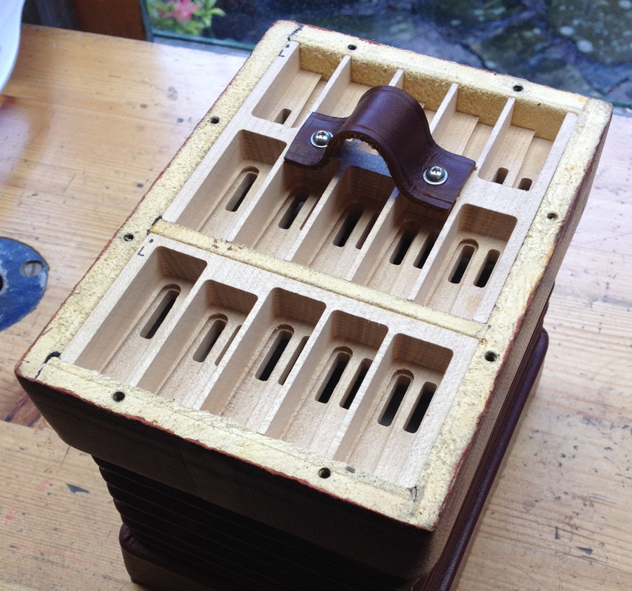
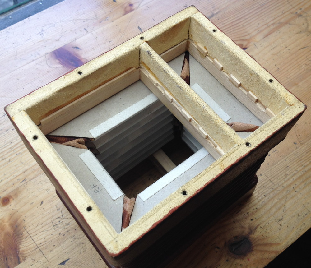
If you’re familiar with more conventional concertina reed pans, you’re probably wondering at this point how you pull out the reed pan (which tends to be a fairly tight fit) without a hole in the middle to put your fingers through. Because I didn’t have any space for the finger hole, particularly on the left hand side, I instead attached captive nut plates on the bottoms of the larger pans and made a leather handle that screws onto the pan.

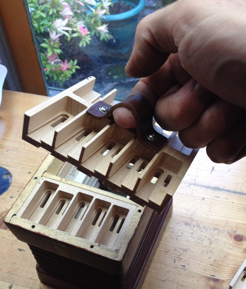
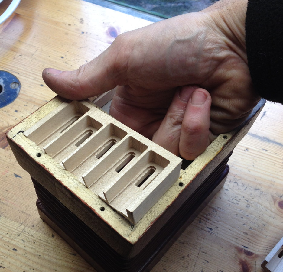
Once you have lifted out the larger pan, you can put your fingers through the hole and push out the small pan from underneath.

Here’s a quick video clip showing the first time the instrument made a sound:

https://www.instagram.com/p/BUKcZ9XDiGZ/

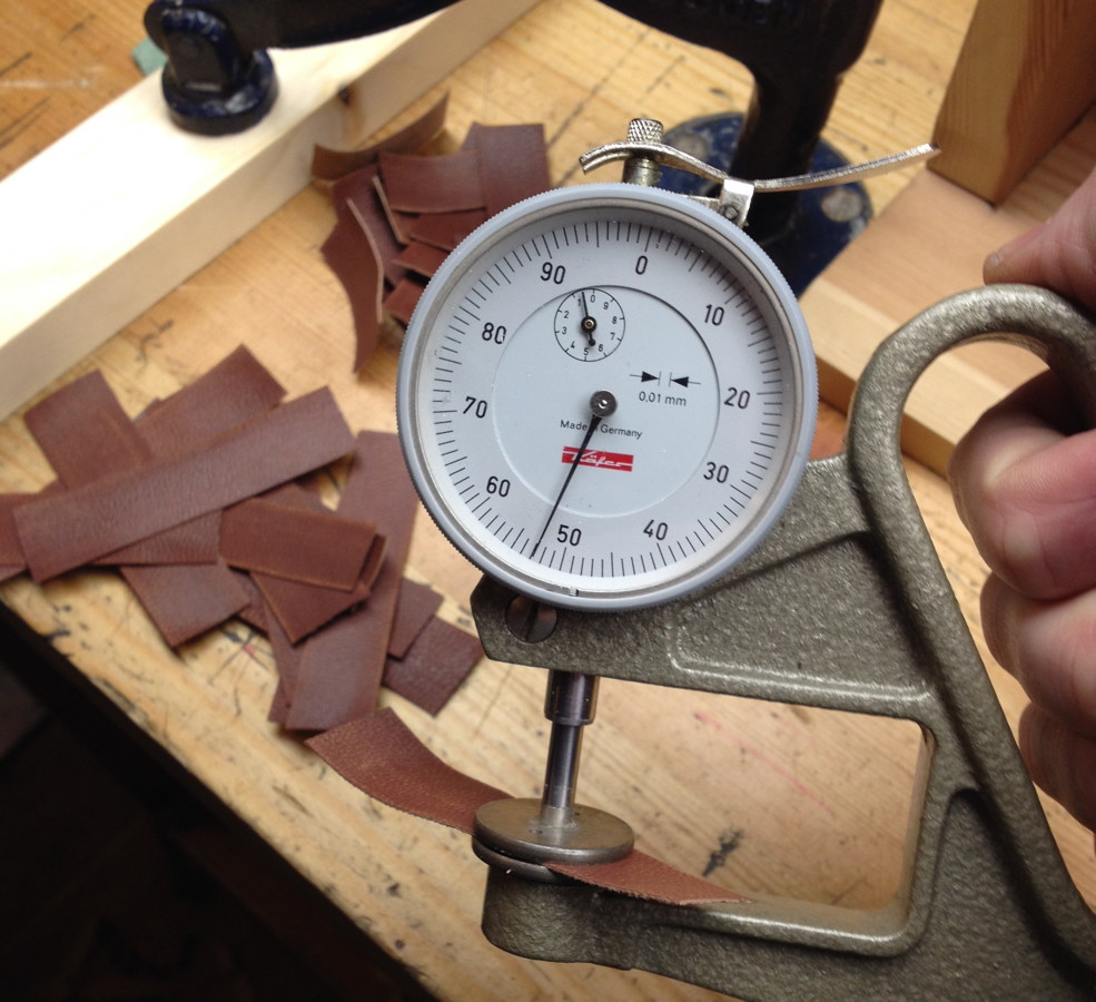
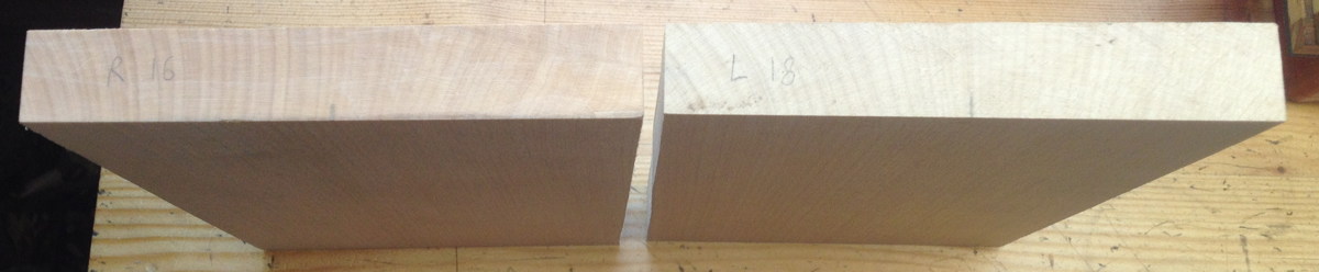
When I made the bellows frames I didn’t know how deep the reed pans were going to be, so I allowed a generous depth of 20mm and put off the decision until later. As it happens, I eventually made the left hand pan 18mm deep and the right hand pan 16.5mm, which meant I then had to add some sort of spacer blocks that stopped the pans going in too deep. I thought I could just make strips that went all the way around, but they fouled on the bottom reed clamps so I had to cut a lot of notches out of them. In hindsight I went about this a particularly difficult and tedious way, and on future instruments I will be reverting to the traditional-style corner blocks instead, preferably fitting them to the frames before the bellows!

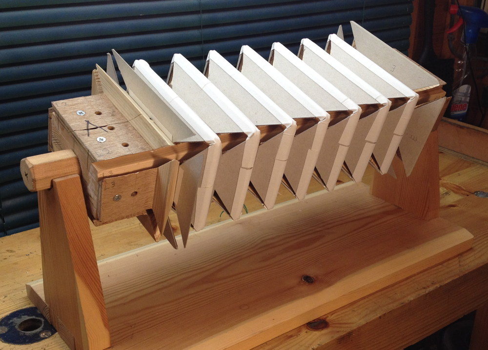
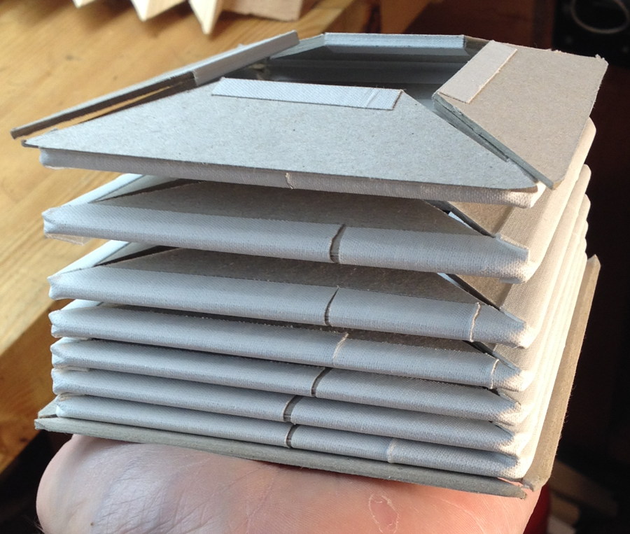
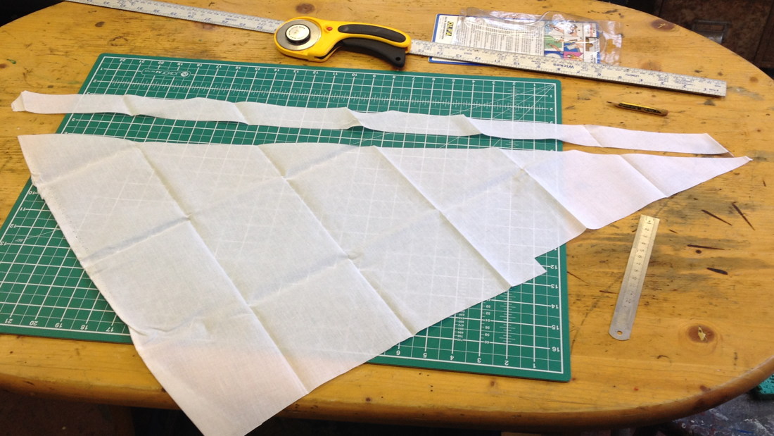
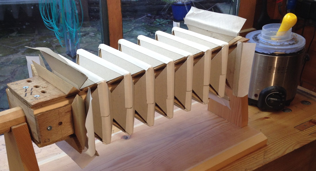
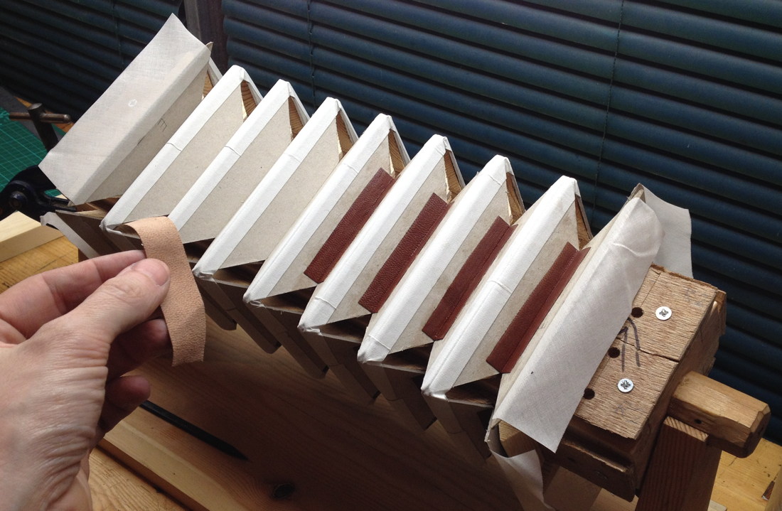
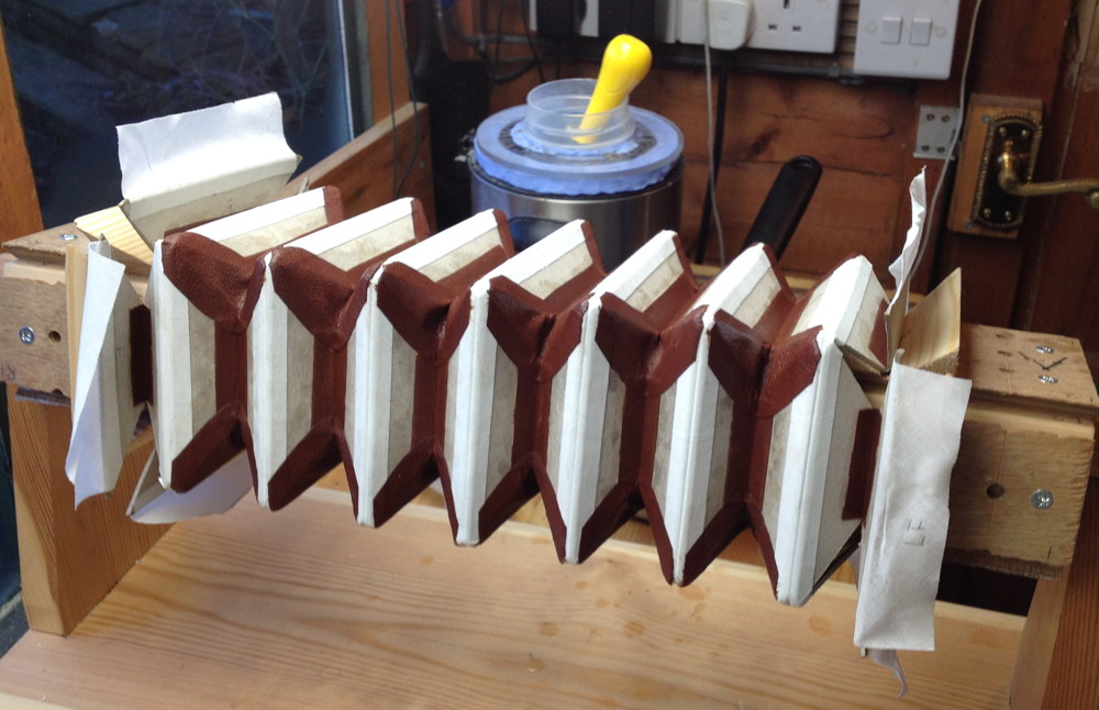
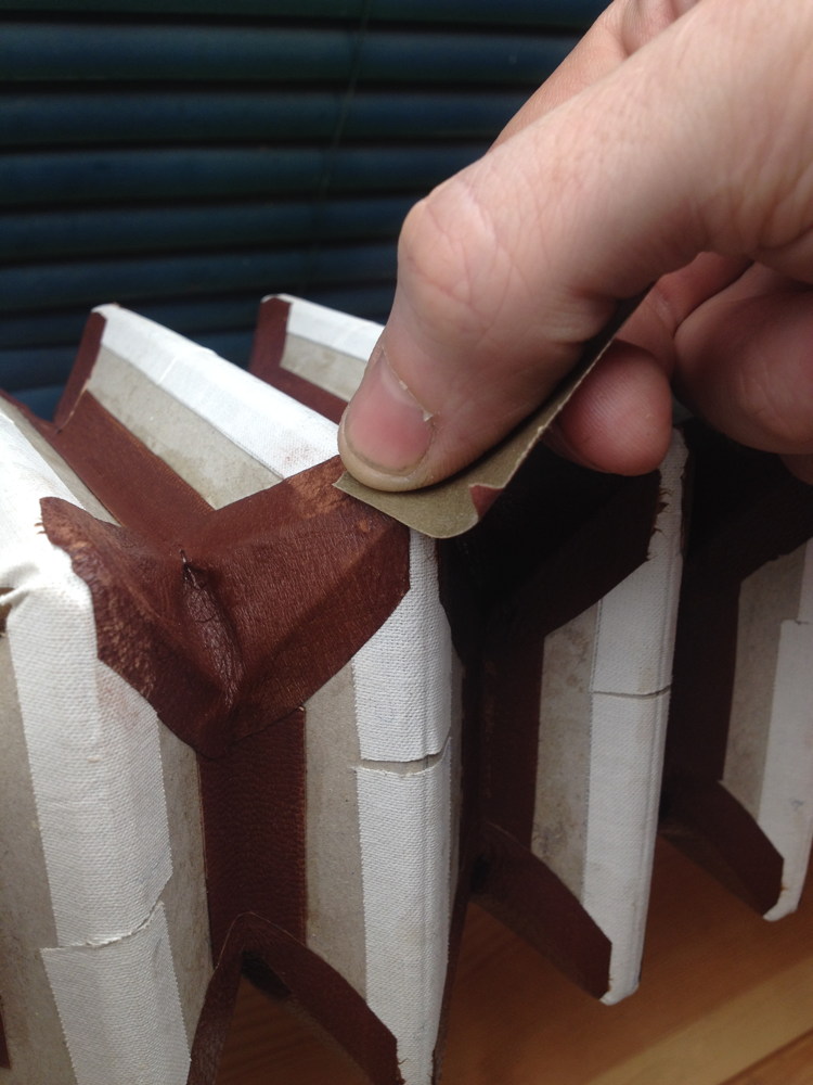
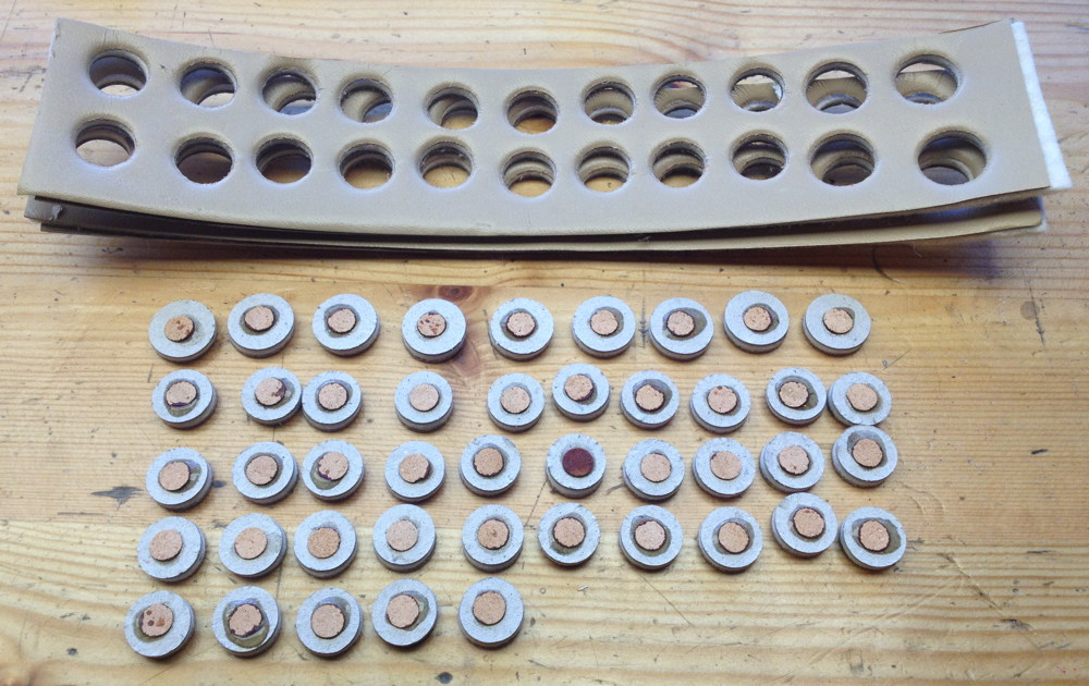
Gluing strips of chamois leather to the tops of the walls with rabbit skin glue. I found that skiving the ends of these strips needs a slightly different technique to skiving bellows leather because the chamois is so soft and stretchy.

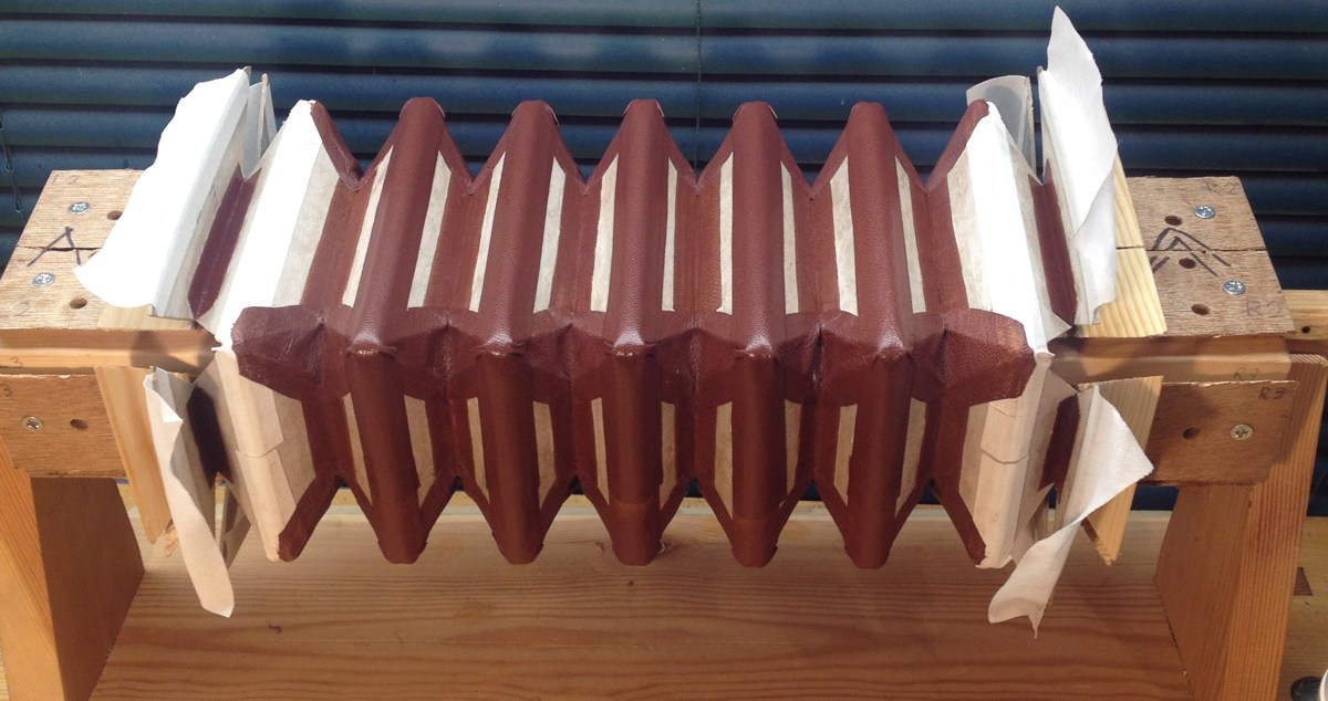
All the gaskets installed.

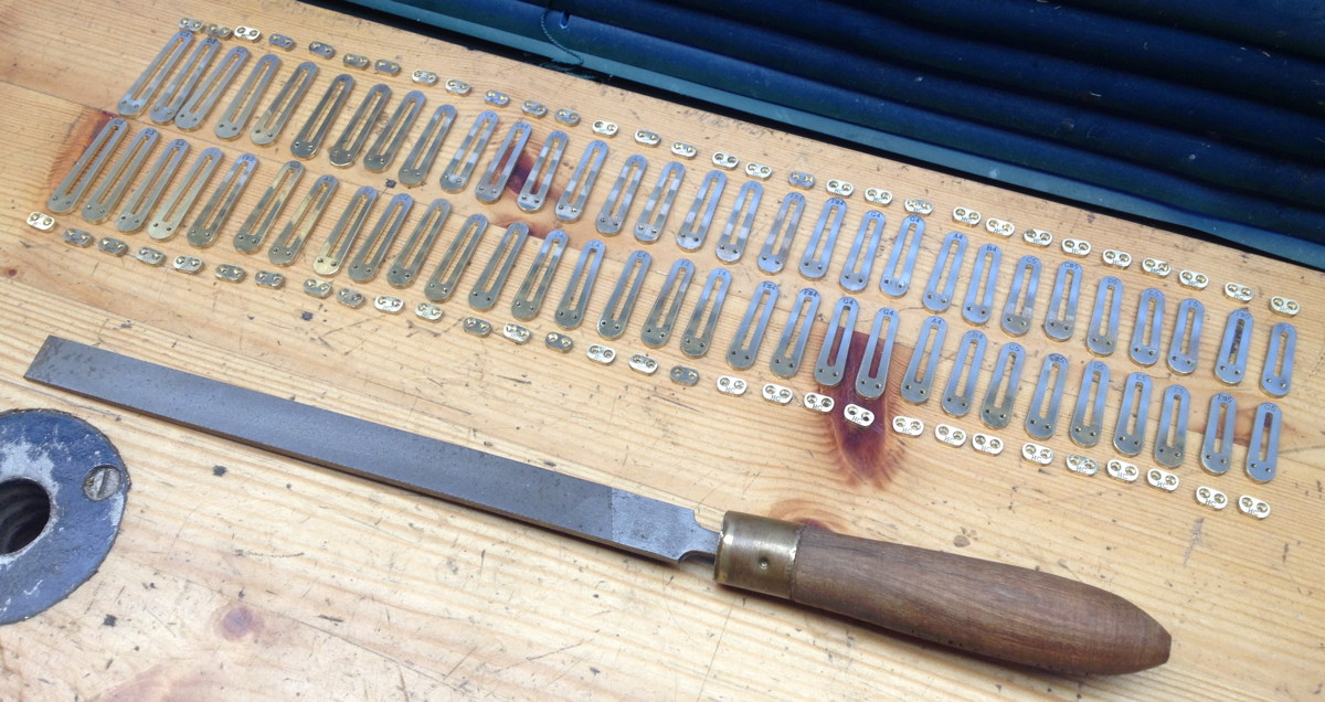
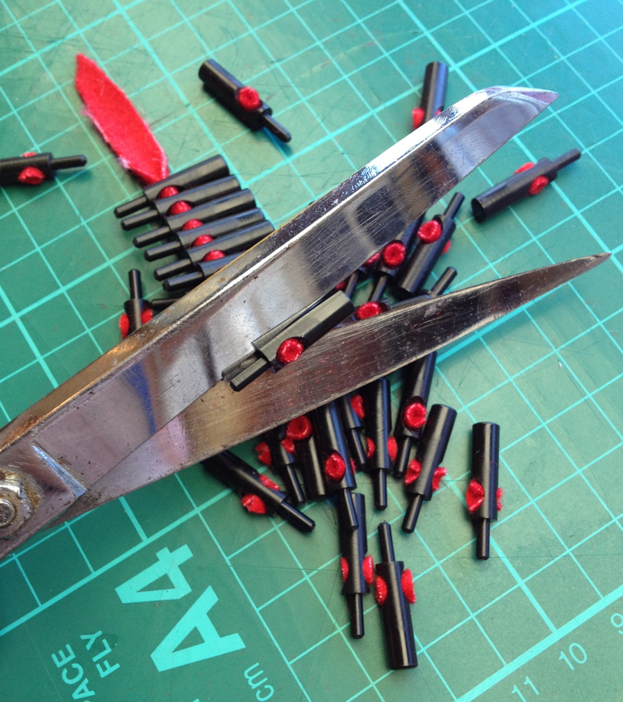
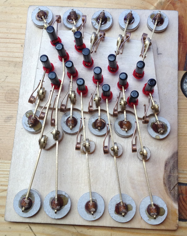
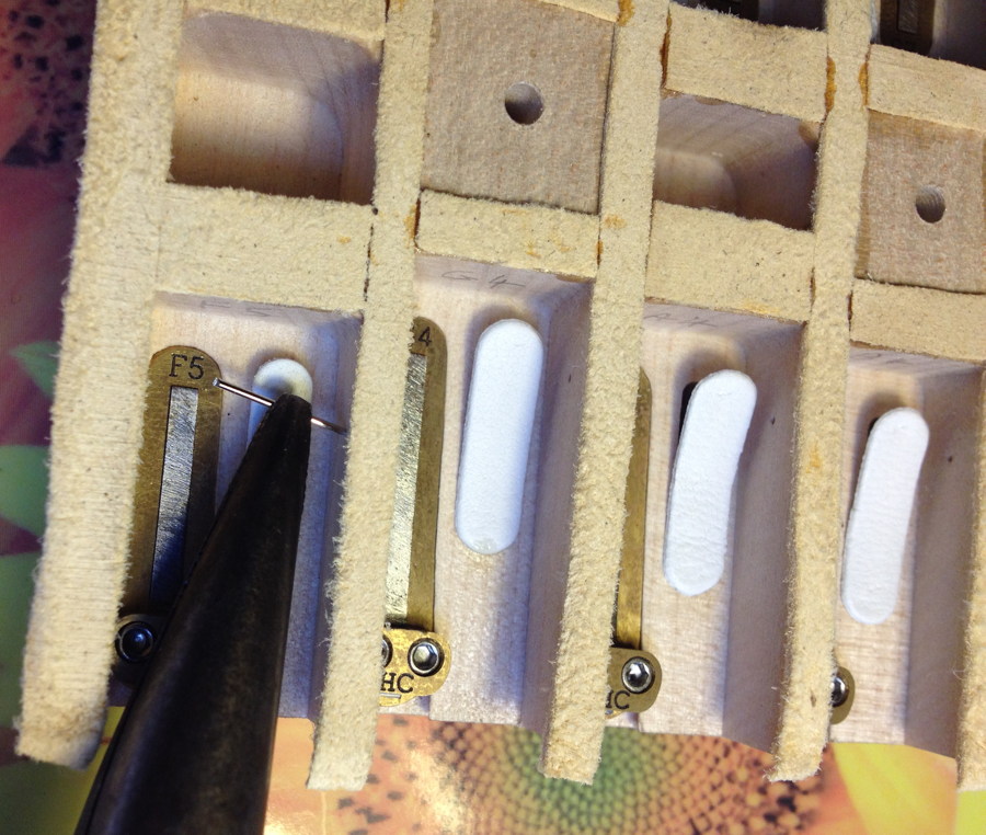
I made the valve restraint pins from chrome plated sewing pins. After struggling to push a few of them through the chamber walls with needle nose pliers, I found they went in a bit easier if I sharpened them on a stone first.

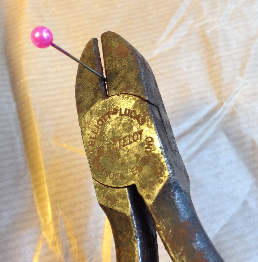
There’s a bit of a knack to deciding exactly where to place the pins, so as to allow the valve to open properly without getting stuck. On my next one I’m planning to try making the pins from a slightly smaller diameter stainless steel spring wire instead.

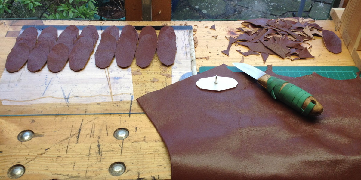
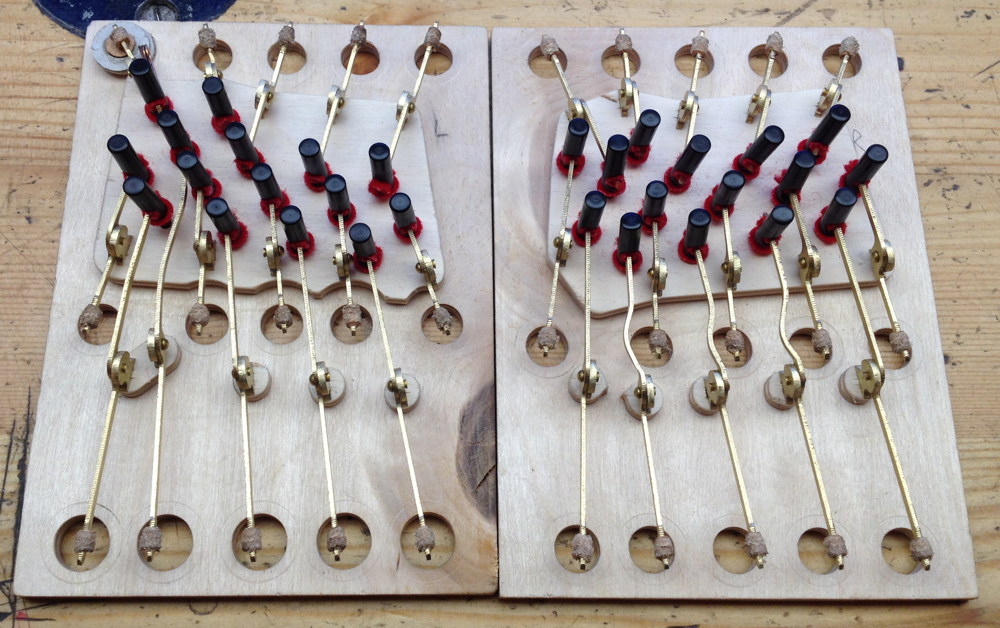
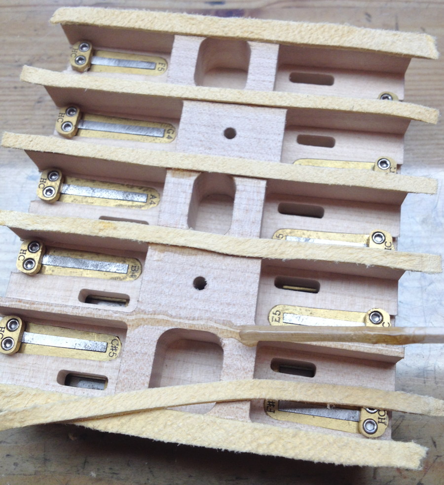
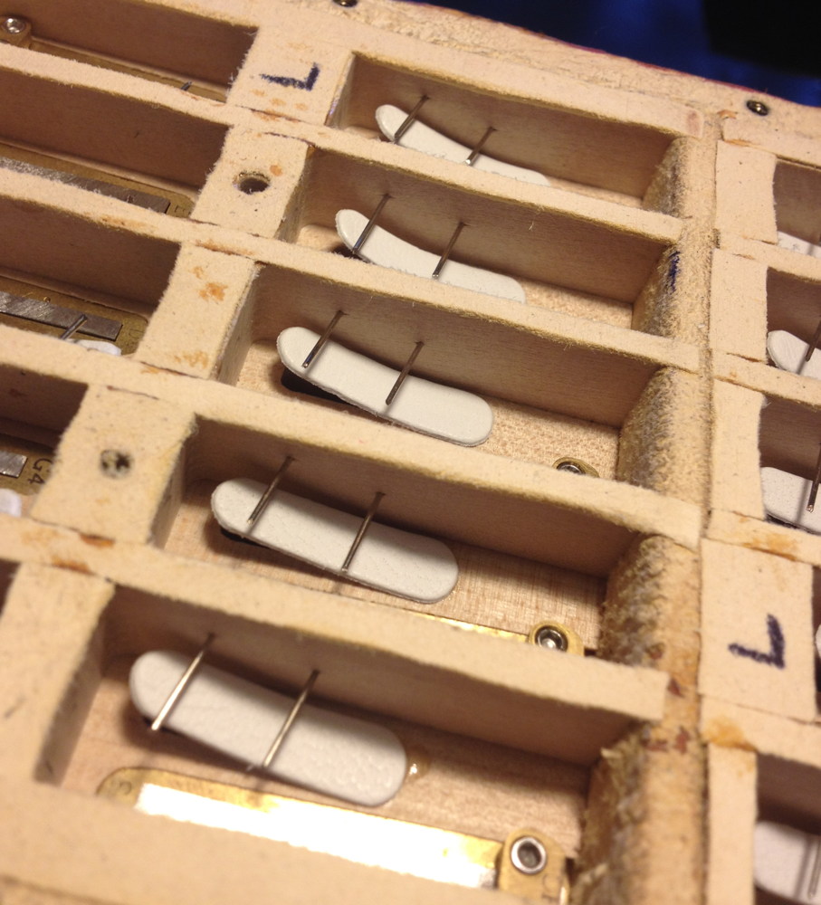
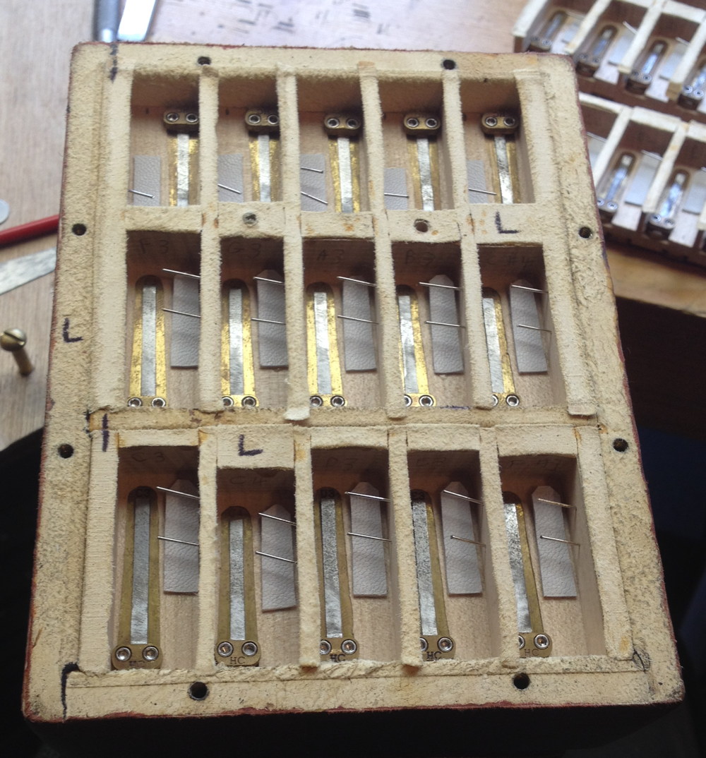
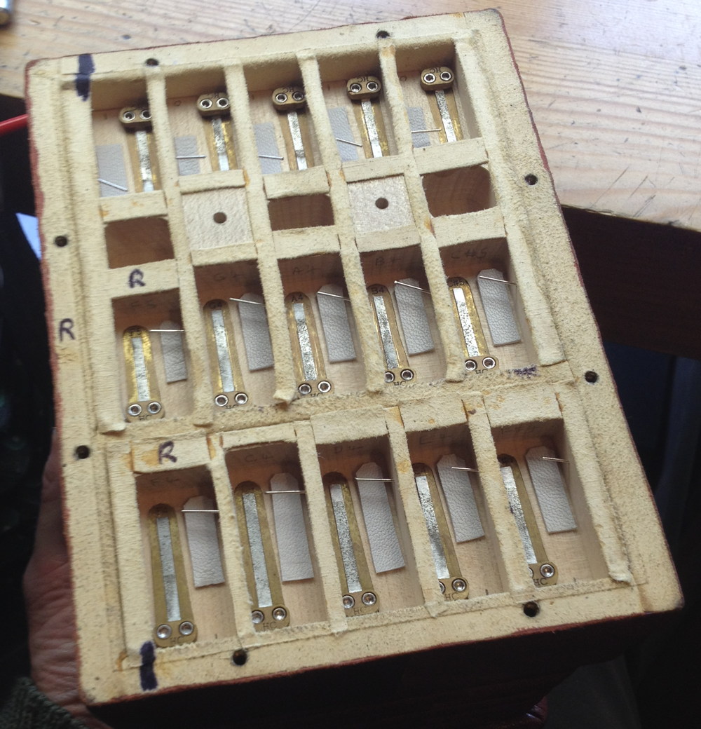
I had lots of problems with the valves. My first attempt, I cut them by hand from sheepskin skiver, and they were terrible. The leather was too stiff, and every note sounded muffled if it played at all. My second attempt, I bought a set of valves from a parts supplier, and I’m not totally sure what the problem was but they didn’t seem to want to stay flat against the pans. This photo shows how some of them have lifted up until they are touching the restraint pins. This caused a problem with the bottom few notes making a sort of ‘raspberry’ noise if you changed bellows direction while holding the button down because the valves weren’t keen to stay closed.

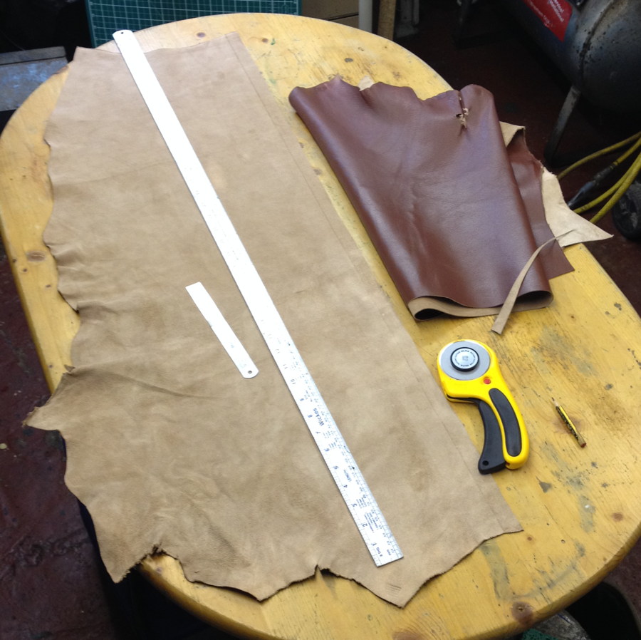
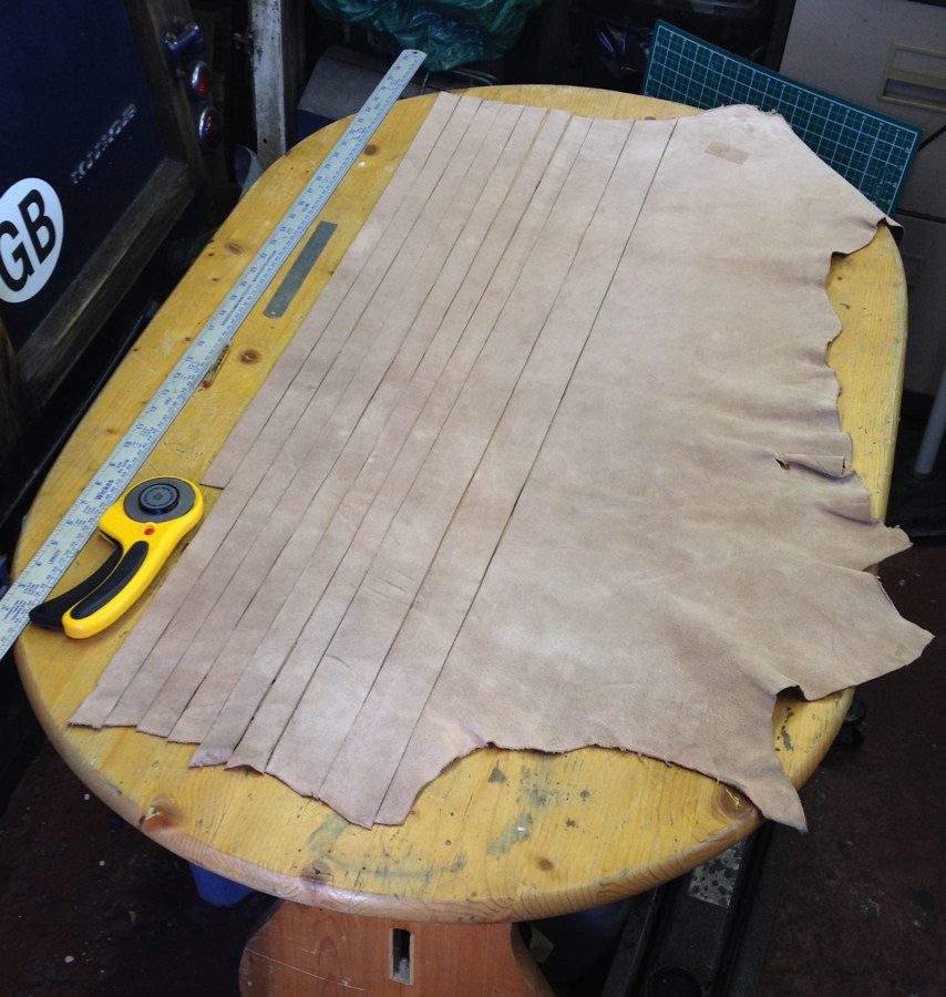
On advice from several other makers, I ordered some hides of Columbia Pneumatic Leather from Columbia Organ Leathers (who are based in a town called Columbia, Pennsylvania, not the Republic of Columbia). It’s not cheap but it’s nice stuff. I removed all the previous valves (I found the easiest way was to just rip them off, then use hot water to remove the remnants of the old glue) and cut a new set, mostly from the extra heavy weight hide, though I did use the heavy weight for the higher notes. It was recommended to me to wash the leather and dry it on a sheet of glass to make it a bit stiffer, but I couldn’t tell any difference before and after washing (maybe I did it wrong). For the most part, the new valves behaved much better and solved the problems I was having. A few of them misbehaved in testing, not always for obvious reasons, but replacing them solved the problem.

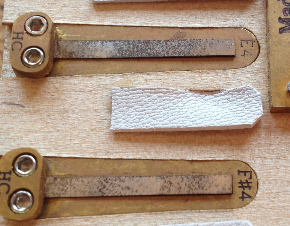
Here’s one of the misbehaving valves where I was able to find the cause. If I played the blow reed, then played the corresponding suck reed very softly, it would start muffled, then ‘pop’ and play normally.

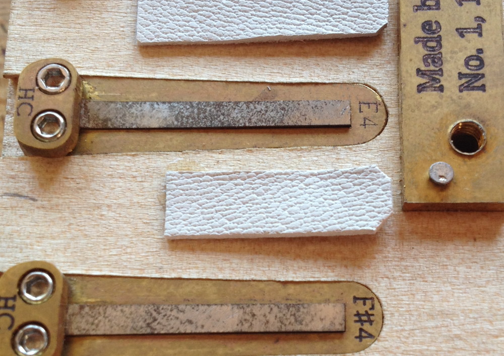
It turned out I had glued it off-centre, and one edge of the valve was getting sucked down into the wind slot.

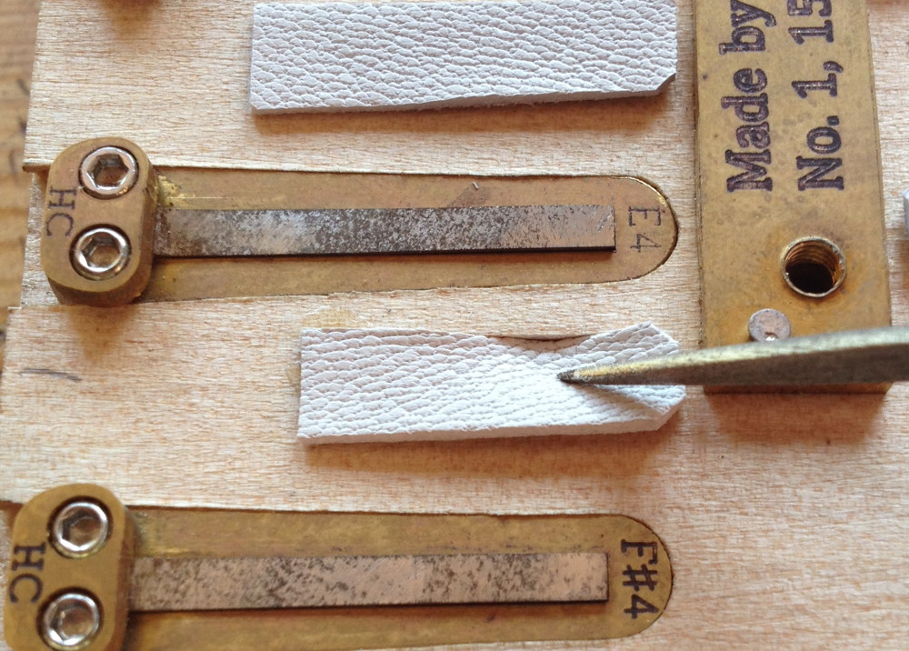
Replacing it in the correct position solved the problem. It’s quite tricky to get them positioned right because you can’t see the slot while you are gluing the valve down. I’ve considered drawing a centre line in pencil first.

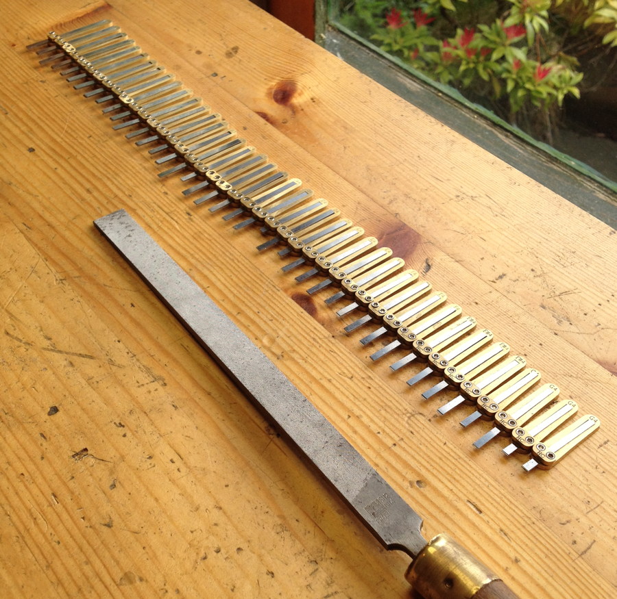
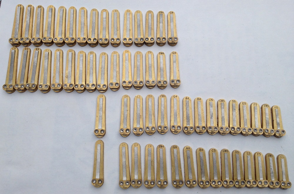
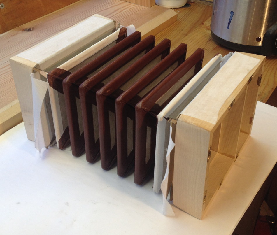
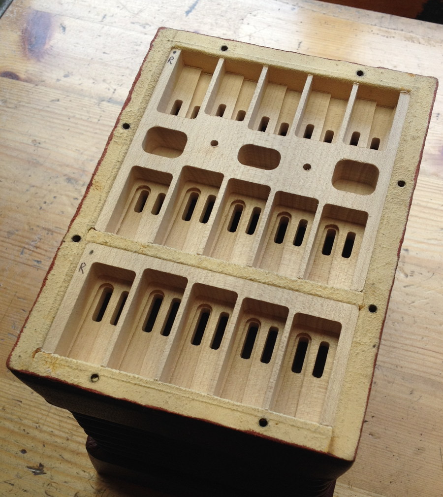
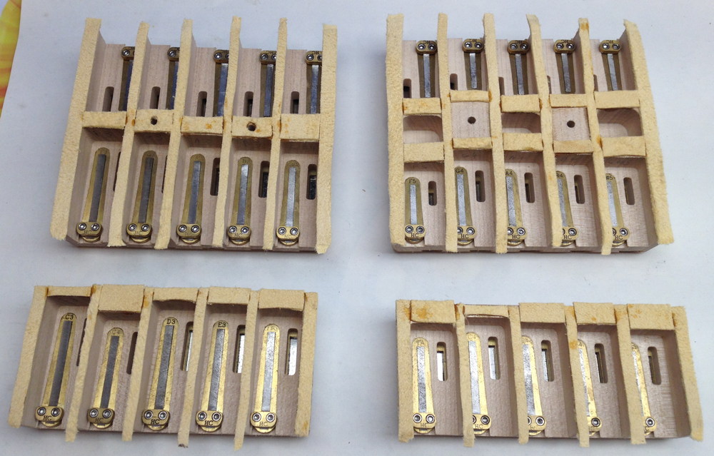
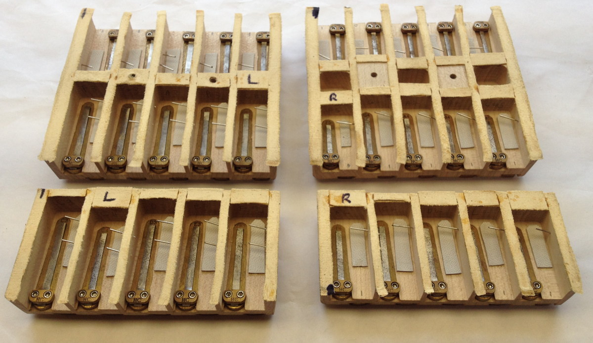
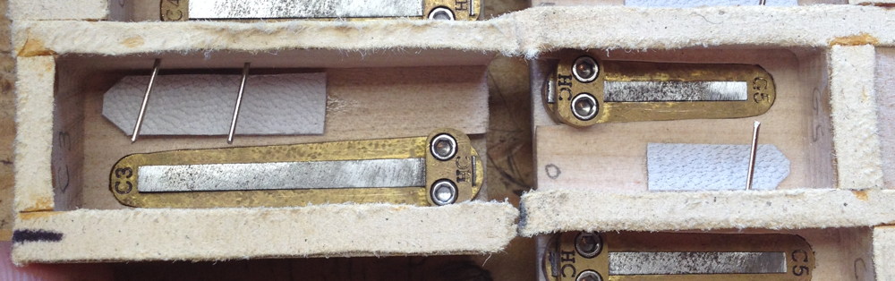
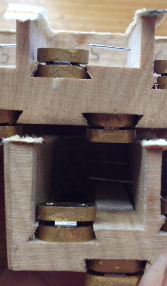
The finished reed pans. Note all the marks in biro indicating where and which way round they fit.

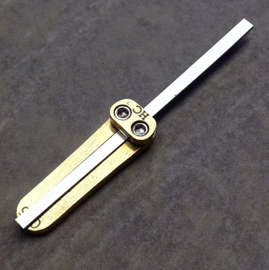
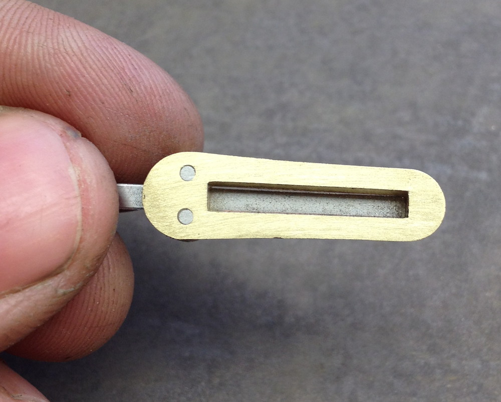
These two pictures show the difference in size between the biggest chamber (C3) and the smallest (G5). In hindsight I suspect I could have made them all a bit smaller, but I was trying to be conservative and working on the theory that a too-small chamber will sound terrible, whereas a too-big one will just start up slowly. In fact, as far as I can tell, they all seem to respond pretty quickly.

The final thing remaining was fine tuning all the reeds, and bits and pieces of troubleshooting: tweaking the action to eliminate ciphers, replacing misbehaving valves, etc. The client asked me to tune the reeds in quarter comma meantone, with G as the root note. I made a quick video clip showing it playing a few chords, though in hindsight this doesn’t really show it off very well. You’ll have to take my word for it that it has a much nicer sound in person than recorded on an iPhone microphone. I hope at some point I’ll get to hear what it sounds like in the hands of a good player.

https://www.instagram.com/p/BWuuyH5DyWq/

No. 1: Brun Part 7: Reed Pans Read More »

No. 1: Brun Part 6: Reeds

The sixth instalment in the story of how I built my first concertina is about the reeds. I’m not going to cover every step of the process because it was very similar to my previous posts on the subject, apart from a few minor improvements and the fact that I had to make sixty of them in twenty four different pitches.

Something unusual I did (it might even be the first time it’s been done by a concertina maker) is I made a different size of frame for every pitch instead of making do with a limited number of frame sizes, each one being used for two, three or even four pitches. I started by measuring the vent dimensions of the reeds in a Lachenal English I own and plotting them on a graph. They were pretty lumpy but they followed a general trend. I then fitted curves to the graph and used them to derive a formula for the reed scaling. I plugged those formulas into a spreadsheet, which calculated the vent dimensions for all the pitches I needed. The outer frames were all the same angle and tip radius, with a constant distance between the tip of the frame and the tip of the vent. A slight drawback with the way I did it is that the longer reeds ended up with thinner edges than the shorter ones; when I design the next set I may try to come up with a way to reduce that effect.

I have since learned that the reeds I based my scale on were probably what is known as “short scale”. A fellow maker sent me a set of measurements of reeds from a higher quality vintage instrument, which appears to have both longer low reeds and shorter high ones, i.e. the range of pitches is stretched out over a wider range of lengths. I understand short scale reeds were typically used when the maker needed to fit a lot of reeds into a given space, which actually makes a lot of sense for this particular instrument because the reed pans are very tightly packed. I don’t think I could have fit long scale reeds in it if I had tried. My next concertina will have the same number of buttons in a larger instrument, so I plan to use longer scale reeds in it. I have been told that longer scale reeds have better pitch stability and responsiveness, particularly on the low end.

As before, I cut the frames and clamps from 2mm brass sheet on my CNC milling machine. This time I left them at the full 2mm thickness.

When I did the prototype reeds, each frame took a very long time to mill. Before I made the first full set I spent a while experimenting with feed rates and depth of cut (wasted some material and broke a couple of end mills in the process), and came up with a reliable rate that is significantly faster than what I was using before. I also dropped what was by far the slowest part of the process: bevelling the edges of the frames with lots of tiny steps. They now come out of the milling stage with straight sides.

The full set of sixty frames and clamps, before cutting them free of the stock.

After cutting them free, I tapped all 120 clamp holes and screwed them together. The clamp is a different size for each pitch too, so it’s important not to mix them up!

I filed off the flashing and the remains of the tabs with a hand file. In hindsight it would have been quicker to use my die filer to clean up the frames, though the clamps are probably too small to do that way.

A little improvised fixture to hold each reed frame while I square up the vent corners with a needle file. It’s crucial to get the tip corners as perfect as possible otherwise you can’t get the tongue to fit really closely without clipping the frame.

The vent relief angles on my Lachenal reeds were very inconsistent and often rounded; I suspect they were quickly filed by eye without a guide. I set my guide to an angle that was roughly the average of the angles on the Lachenal reeds and used it for all of my reeds.

I used my die filing machine with the table tilted over to 7.5° to bevel the frame edges, filing up to a line engraved by the CNC mill. I deliberately left them a bit on the tight side, then later on after I’d made the reed pans, I hand fitted each frame to its slot with a hand file.

https://www.instagram.com/p/BTTeGiqjHiH/

I shortened the clamp screws by first clamping the reed tongue blank in the frame, then grinding the screws almost all the way on a slow grinding wheel, followed by lapping them flat on a piece of fine emery paper glued to a sheet of glass.

All the tongues roughly sheared to size.

Draw filing the edges of the tongues to clean them up, then fitting them precisely to their frame with the aid of my microscope. This is probably the most difficult and painstaking part of the process to get right.

All the tongues initially fitted to their frames; many hours of work have gone into them at this point.

My file was feeling pretty dull so I had a look at it under the microscope. All the teeth had their edges fractured off. No wonder it wasn’t cutting so well any more!

I probably should have bought a new file at this point but I kept going and did much of the profiling with it (I also used a three square file for some of the work). I can’t remember if I’ve written about the fixture in this picture before. It has an adjustable-height step that you place the tongue against. The clamp is a pair of locking pliers that have been modified to have a sharper nose.

The full set of reeds, profiled and rough-tuned. They start out very high initially and go lower as you profile them. I stopped filing when they reached somewhere between +5 and +20 cents sharp on the tuning bench, knowing that they were likely to go a bit flatter once in the instrument. The way they are arranged in this photo shows the unisonoric reed pairs for the left hand on top and the right hand on the bottom, with a few notes of overlap in the middle. If it was an English or Anglo concertina the distribution would look very different.

It’s been said by other makers that, of the many time-consuming stages involved in making an English-style concertina from scratch, the reeds are the greatest. I think I can definitely agree with that statement. I probably spent at least a couple of hours on every reed, maybe more when I include time later spent troubleshooting and fine-tuning.

No. 1: Brun Part 6: Reeds Read More »

No. 1: Brun Part 5: Bellows

The fifth instalment in the story of building my first concertina is about the bellows. First I had to make a new, rectangular mould to assemble them on. The stock for the forms was constructed from strips of softwood glued across a plywood base, which I then ripped into four pieces.

I again milled the forms to shape on the CNC mill. One thing I did differently this time was to rough them out in staircase form with an ordinary ¼” end mill first before cleaning them up with the large V bit.

When I made the forms for the hexagonal mould, I cut straight into the material with the V bit using lots of shallow passes, which caused lots of noise and vibration, resulting in a poor surface finish. Removing most of the material with an end mill first gave much better results.

The wide forms stretched the machine to the absolute limit of its Y axis capacity.

The bandsaw I had at the time wasn’t capable of ripping the angles off the undersides of the forms, and I don’t own a table saw, so I did them with a hand rip saw instead.

The rectangular core was relatively simple to make compared to the previous hexagonal one.

I split both of the long sides to make the mould easy to remove from the finished bellows.

Cutting the cards by hand with a craft knife. I hate this part; it makes my knife hand ache for days afterwards. Also, because this set of bellows was meant to be relatively heavy-duty for a ‘travel’ instrument, I chose to use thicker 1.5mm card rather than the standard 1mm stuff I used on the tuning bellows (in hindsight this may not have been a good idea because it made the bellows a bit bulkier). I have since bought a special card cutting guillotine that in the future will make this operation much quicker and easier.

Rounding the corners of the cards with a gouge. I started off pressing down onto the bench, but I found it was easier to put a cutting board in the vice and lean against the gouge handle with my hip.

I rounded the tops of the cards on a linisher (bench mounted belt sander) with an 80 grit belt. In hindsight I should have done this outdoors because everything in the garage including my car wound up covered in a thick coating of fine grey dust!

The rounded top of a card. This gives a nice shape to the peaks of the bellows folds, though in hindsight it would have looked better still if I had rounded the pointy corners a bit more.

I decided to try hinging the cards together with a self adhesive linen hinge tape made for bookbinding and other card related crafts. The roll was quite wide so I cut it in half. This picture shows the result of a strength test: the surface of the card ripped off before the glue or the linen failed (and it took quite an excessive amount of force to do so).

I started by hinging the cards together on the inside. The peak hinges can be taped with the cards laying flat, but it’s better to do the valley hinges with each pair of cards in the closed position (or flat but with spacers holding a slight gap between them), otherwise they will later resist closing.

I folded them up and clamped them tightly like this for a couple of days to help the tape glue to really bond well to the cards. Note that the end cards are slightly taller because the end boxes are about ¼” bigger than the bellows. This is partly cosmetic and partly to avoid the bellow peaks touching the table when you put the concertina down.

Next I tied the sets of cards to the mould with plastic coated gardening wire. Elastic bands would probably have been easier but I didn’t have any long enough. Note that the bellows frames aren’t attached to the mould. This wasn’t possible with this instrument because the frames have a divider across them due to the split reed pan design.

I ran the self adhesive linen tape all the way around each peak. This gives a stronger bellows than if you just put small pieces on each corner.

Afterwards I took the full set of cards off the mould and again pressed it tightly for a day or two to help the top hinges stick as well as possible. You can see in this picture what I meant about how it would have looked neater if I had rounded the corners of the cards a bit more.

I needed wider hinge strips on the end cards to attach the bellows to the frames, so I cut those from the ‘Fraynot’ hinge linen from Shepherds bookbinders’ suppliers that I used for all the hinges on my tuning bellows. I cut it on the bias to make it less likely to fray or rip.

Then I glued them on. From this point on, I used hot rabbit-skin glue for everything except the decorative papers.

A brief digression about my experience with the self adhesive hinge linen. In future I’m going to go back to using the Fraynot linen cloth for everything. Although the self adhesive tape worked fine and I don’t think it’s likely to come apart, I found that I much prefer working with the Fraynot and a liquid paste/glue, because if it goes on wonky you can peel it straight off and reposition it, whereas the self adhesive tape sticks instantly and you have to tear the surface of the card to get it off again, then throw away that strip of tape. The tape is surprisingly expensive too, though that’s not my primary consideration. It also had quite a lot of wrinkles in it where the cloth had stuck to itself during manufacturing and the glue is so strong it’s not possible to pull the wrinkle out; sometimes I had to waste a section of it to avoid putting a wrinkled piece on the bellows where it would be visible through the leather. Most importantly, I believe the hinges I get with strips of cloth are noticeably thinner and more supple than with the tape. The difference is fairly subtle when looking at a single hinge, but an entire bellows set with hinges on both sides of the peaks feels relatively stiff and bulky when assembled with the self adhesive tape. Although it’s possible the tape is made from a heavier cloth, I suspect the main difference is in the properties of the glue. I have found that traditional wheat paste doesn’t noticeably stiffen the hinge at all, whereas rabbit glue does stiffen it a little initially but after working it for a while it ‘breaks in’ and becomes supple again. Whatever is on the self-adhesive tape has a rubbery feel to it, and seems to add a bit to the thickness of the hinge too.

I covered the bellows with a nice brown goatskin leather from Hewit, cutting it into strips with an Olfa rotary cutter, which really cuts very nicely, much easier to use than a craft knife.Using my Scharffix 2000 to pare the leather down.

Thanks to a thread on the concertina.net forum, I learned that Israeli-made Personna safety razor blades fit the Scharffix and cut really well, better even than the thicker OEM blades that came with the machine. It’s crucial with this machine to use ultra-sharp blades, otherwise it behaves terribly, stretching and ripping holes in the thin leather.

Checking the thickness of the valley strips.

And gluing them on:


Cutting out the gussets with a template and craft knife. This is rather a tedious job; a die tool would make it much quicker.

I use the Sharffix to do as much of the skiving as possible, but the gussets always need a bit of manual cleaning up afterwards with a skiving knife.

Gussets glued on. It proved rather a pain to get the bottom corners to fully stick to the valleys without leaving a little gap. I wound up waiting for them to initially dry, then adding a bit more glue to each gap with a tooth pick and pressing it down with a bone folder until it stayed in position. This is less of a problem with bellows that have more than four sides because you don’t have to stretch the gussets around such a tight angle.

I roughed up the tops of each gusset slightly with sandpaper before gluing the top runs over them.

Cutting more long strips of leather for the top and end runs. It’s a pain when the Scharffix goes wrong in the middle of one of these strips because you need the whole run to be good to avoid having more than one joint.

Top runs glued on.

Next I needed to take the bellows off the mould and attach them to the frames, starting with the hinge linen.

Now the end gussets. This was way more difficult to do neatly without the aid of a mould. It helped to use a stick clamped to the frames to hold them a fixed distance apart.

Finally the end runs. As I mentioned in part three, here’s where I realised I’d made a mistake in not making the bellows frames a tiny bit smaller than the action boxes, in order to hide the edge of the end run. I skived the edge down as close to nothing as I could and tried to get that skived edge flush with the edge of the frame, but it was impossible to get it absolutely perfect, so when I subsequently trimmed the extra off, the edge wasn’t infinitely thin any more so it is possible in places to see a tiny bit of unfinished leather. I recognise I am quite possibly being over-critical of my own work here!

Looking pretty good!

For the decorative papers, I took a sample of the leather down to my local craft shop and looked for a patterned decoupage paper that went well with it. This is what I found. I avoided cutting papers from the area near the bottom that looks dirty (the design is actually printed that way).

I spent a pleasant evening cutting out papers and pasting them on while watching TV programmes in the background.

The finished bellows. I think the papers really go quite well with the leather. Although they were still quite stiff and springy at this stage with a preference for remaining open, I subsequently spent quite a while pressing them and exercising them, and they gradually broke in and became easier to play.

No. 1: Brun Part 5: Bellows Read More »

No. 1: Brun Part 4: Actions

Part four of the story of how I made my first instrument is about the actions (i.e. the mechanisms that uncover holes and let air through a reed when you press a button).

I made the action boards from birch plywood on the CNC milling machine, which seemed to work pretty well. Although I’m sure high-quality plywood is a good choice for strength and stability, on the next instrument I may try making the action boards from solid wood instead to see if it has a beneficial effect on the tone.

Another thing I will probably do differently next time is to not drill the button peg holes at this stage using CNC. They need to be very accurately aligned with the button holes in the end plates for the buttons to work smoothly, and by doing it this way it took me a lot of fiddling about to get the two boards to line up well enough to avoid the buttons sticking. I think a more accurate way would be to bolt the action boxes together with the action boards inside, then use the pillar drill and spot through the end plate using a drill bit glued into a mandrel that is the same diameter as a button (not my idea: I recently heard about this technique via another maker).

The action boards sit in a rebate in the bottom half of the action boxes. The problems I had with the walls not gluing up perfectly square meant I had to make careful adjustments to the edges of the action boards to get them to fit snugly in the rebates while also accurately aligned with the button holes.

I turned a couple of cylindrical brass dies that mark a circle around each pad hole to help glue the pad in the right place.

Lots of pads.

I made a couple of button guide boards to hold them in the right place while gluing the pads on.

Fitting the cross hole bushes in the buttons (see my earlier article about how I made them) using Bob Tedrow’s method of pulling a strip of cloth through them all, then snipping them apart with scissors:

I cut the lever posts from 1.5mm brass on the CNC mill:

And the levers themselves from 1mm brass:

It took quite a lot of fettling with needle files and emery paper to clean them up. I put the pivot points at the half way points for reasons that made sense on the drawing board, however I have since learned that it is better to put them closer to the button if you can find the space to do so (this causes the pad to lift up by more than the distance the button travels down). In hindsight this may have helped with some of the issues I later had with ciphers because I could have reduced the button height by 0.5mm without compromising the amount of pad opening.


I already wrote about the die I made to thread the grommet ends of the levers, but I have since learned that I get a cleaner, more consistent result from it if I squeeze the tool in a vice instead of hitting it with a hammer.

Before and after forming the threads:

Riveting went fairly smoothly. I only had to redo a couple of them because the pivots tightened up.

The reason for the odd shape of the lever posts is so I could knock them in or pull them back out using a tool with a matching notch cut in it (not my original idea).

The tool has a flaw: because the socket is on an edge of the tool but you hit it in the centre, the force is transmitted to the post off-axis, which tends to cause it to go in at a slight angle. I had to straighten up each post with needle nose pliers after knocking it in. I will probably modify or remake the tool before the next instrument to prevent this happening.

All the levers and buttons installed. Unfortunately I discovered a significant problem at this point. The button ends of the levers were too fat, making them very stiff, especially on the shortest ones.

I didn’t want to pull them all out again, so I instead used a rotary burr and needle files to slim them down in situ, which solved the problem.

Some of the springs.

An action board with all the springs and pads installed. Some of the spring locations proved problematic due to lack of space around the middle row of pads, and I wound up spending quite a bit of time working on getting the button pressure consistent across the instrument while also eliminating ciphers (notes that don’t stop playing when you let go of the button). Most of the ciphers were caused by the end of a lever or part of a spring hitting the underside of the end plate; there was really almost no wasted height inside the boxes.

Adjusting the heights of the buttons to get them consistent is done by bending part of the lever it’s attached to. To make this easier I made a pair of special tools from old screwdrivers to grip the levers in situ.

Overall, I’ve learned that there’s nothing tremendously difficult about building a concertina action, but there are lots of little parts to make and it takes a great deal of patience to assemble and adjust it until it works smoothly, consistently and reliably.

No. 1: Brun Part 4: Actions Read More »