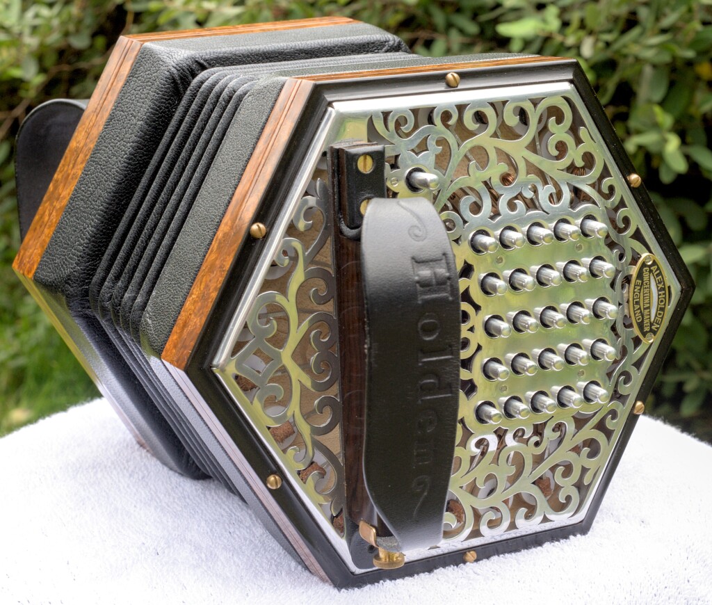
The tenth instrument I built was another Crane duet. It was for John Thornton of Hampshire, the same client who commissioned No. 4. I am fortunate to have several customers who, after receiving their first Holden concertina, immediately placed an order for a second one. No. 10 is very similar in many ways to No. 4, with one obvious difference (metal instead of wooden ends) and a lot of small differences that I will list later. You might find it interesting to read my article about No. 4 as background to this article.
In this video, John performs five tunes on No. 10 and talks a little about his modifications to the standard Crane duet layout.
Specification
- 45+1 button Crane layout with Butterworth curve and slightly narrowed column spacing.
- Six sides.
- Weight: 1260g.
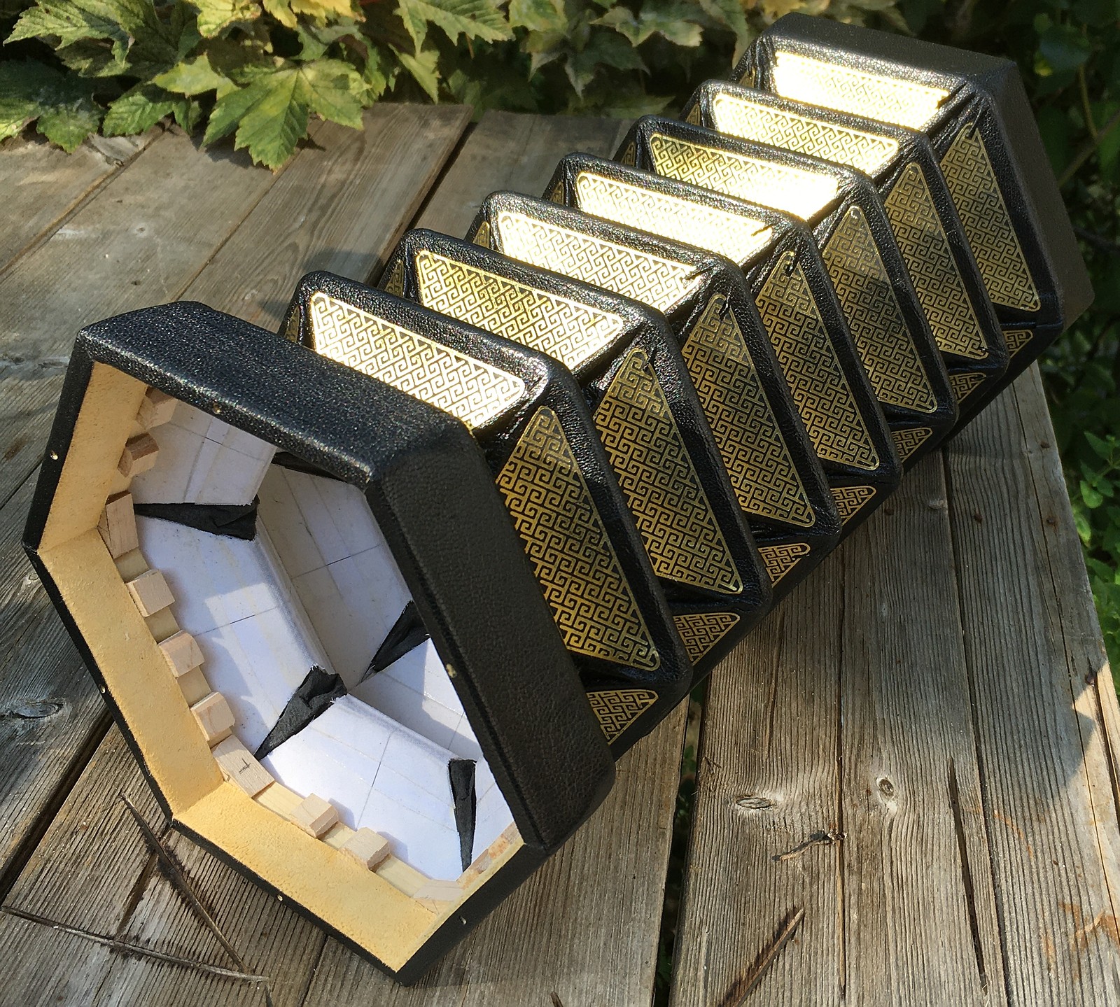
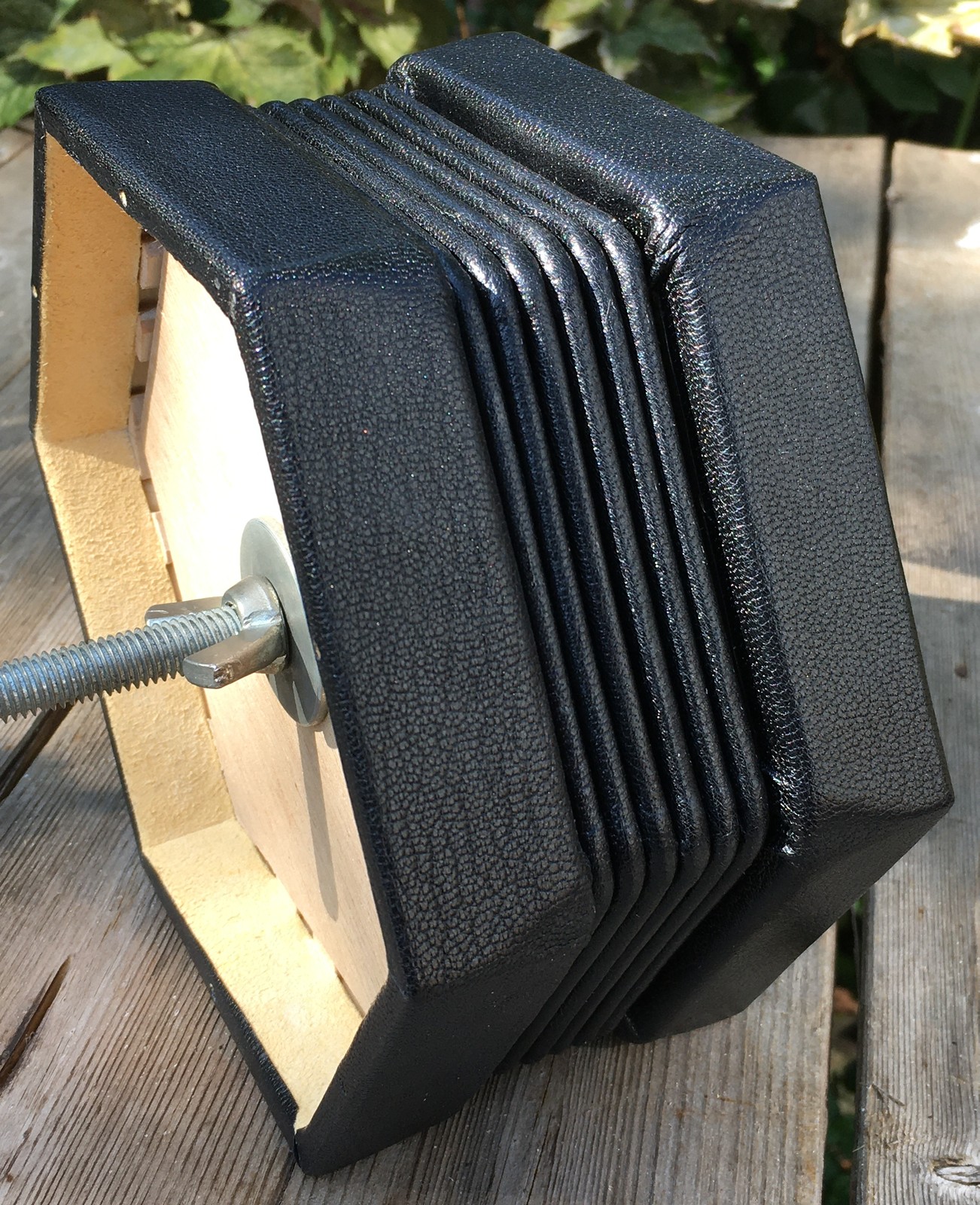
- Six fold black goatskin bellows with gold on black Pictish key pattern papers.
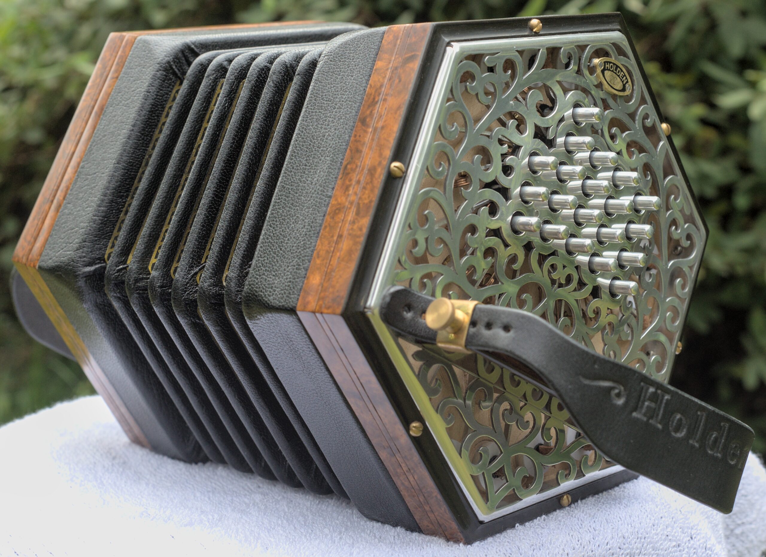
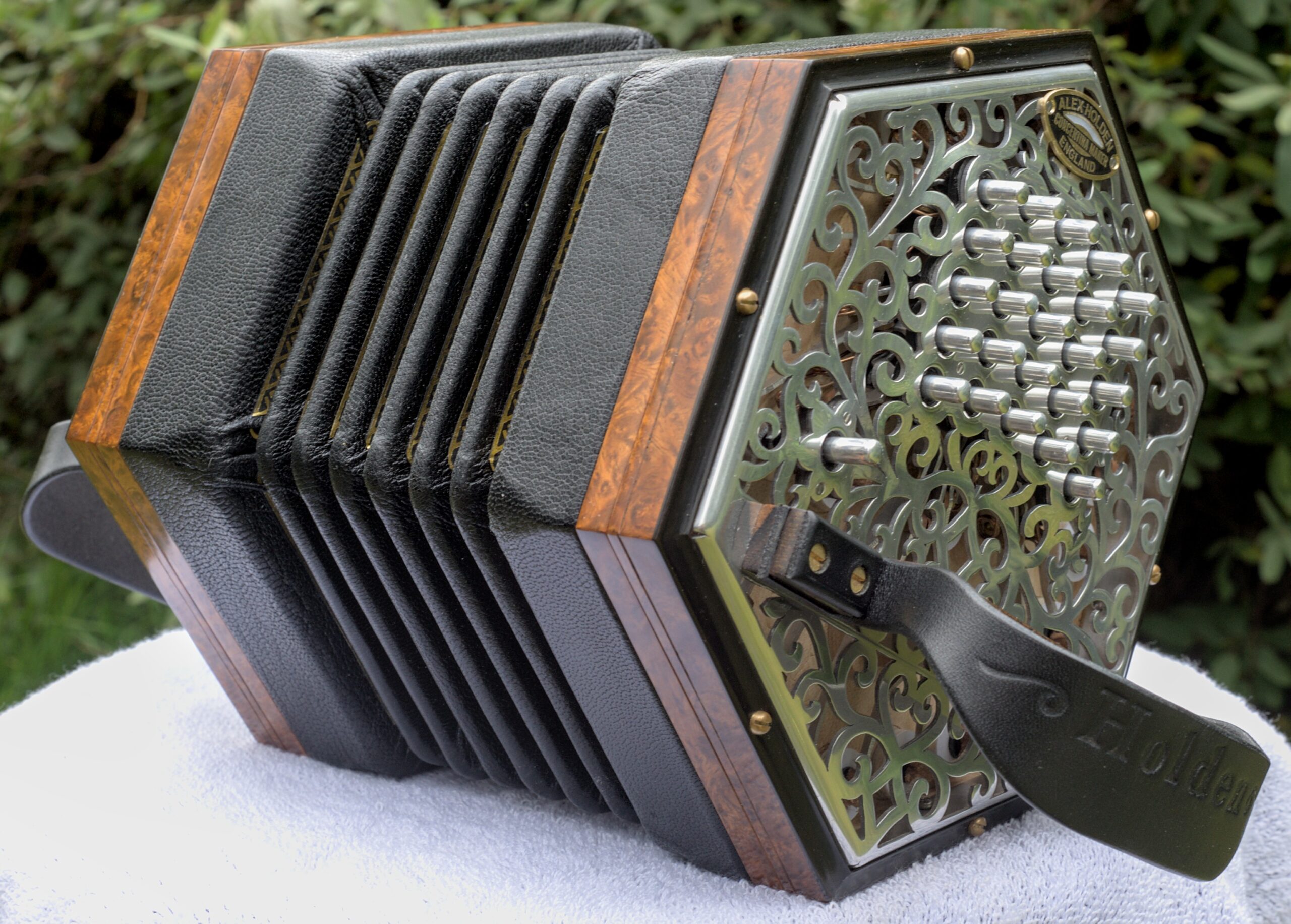
- 1.2mm thick 5251-H22 inset aluminium end plates with folded edges and concealed mounting screws.
- Amboyna burl veneer with black Rocklite Ebano borders, moulded in traditional ogee profile.
- Ziricote handrails with integral strap fixings.
- French polished finish.
- 6082-T6 aluminium reed frames with steel reed tongues.
- Standard scale reeds on the left hand, long scale on the right hand.
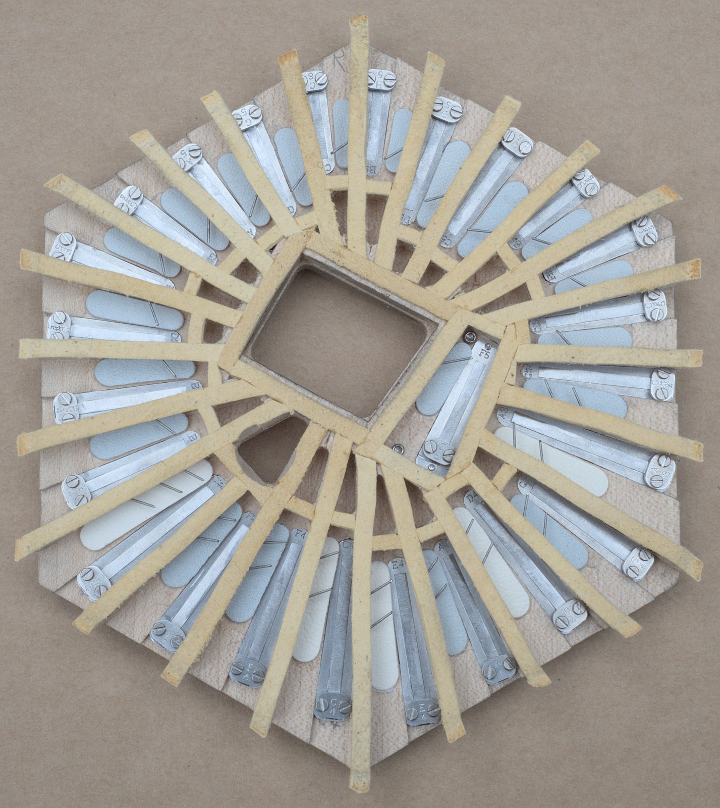
- Sycamore radial tapered reed pans.
- Sycamore action boards.
- Aluminium riveted action levers.
- 3/16″ solid aluminium buttons.
- 2mm button travel (giving 4mm pad lift at 2:1 action lever ratio).
- Black wool bushings.
- Tuning: 1/5 comma meantone with root note A=440Hz.
- Includes some modifications to standard Crane layout, such as the addition of left hand G2, A2, and B2 notes, and right hand A3 and B3.
Here is the button layout of No. 10 (click to enlarge):
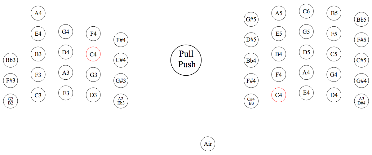
Something John didn’t mention in the video is the reason why it has only 45 buttons instead of the standard 48: 45 is the most I could practically squeeze into a 6 1/4″ wide instrument, and we didn’t want to make it larger just for the sake of including three very high notes. Both No. 4 and No. 10 are significantly smaller and lighter than a normal 48 button Crane, while John’s Anglo-style modifications to extend the range downwards on both hands and the Eb4 → A4 swap on the left hand make it more musically useful. The three missing notes are the D, E, and F at the top of the range, which are getting close to dog-whistle territory and are probably rarely touched by most players. No. 10 is the same physical size as a standard English 48 button treble, but its lowest note (G2) is an entire octave lower. In other words it has the same range as a 48 button baritone English in an instrument the size of a 48 button treble English, it has an octave of overlap between the hands (LH goes up to A4; RH goes down to A3), and it probably weighs less than most vintage trebles!
Although No. 4 and No. 10 are superficially very similar apart from the end plate material, there are actually quite a few differences:
- It has raised inset aluminium ends instead of flat wooden ends.
- The buttons are solid aluminium instead of hollow nickel silver.
- The action levers are aluminium instead of brass.
- The action box wall veneer is amboyna burl instead of walnut.
- I squeezed in an extra A4 button on the left hand without increasing the overall size.
- It has some other small changes to the button layout that make one or the other instrument slightly better suited for playing in certain keys.
- It has deeper bellows cards that give it approximately the same air capacity with one fewer fold.
- It has fancy gold-foiled bellows papers instead of plain black.
- It has an etched brass maker’s plate instead of a paper label.
- It has an etched brass serial number plate.
- It has figured ziricote handrails instead of plain black-stained beech.
- The hand rails are slightly taller to account for the raised keyboard.
- The strap thumb screw is a different shape.
- It has many small internal design/constructional improvements.
- It is about 90g (3 oz) heavier.
- It was supplied in a deluxe hand-made hard case.
- There seems to be a slight (unintentional) difference in tone between the two, but it is quite subtle and almost impossible to describe. It is also perhaps unfair to compare a brand new instrument to one that has been thoroughly broken in.
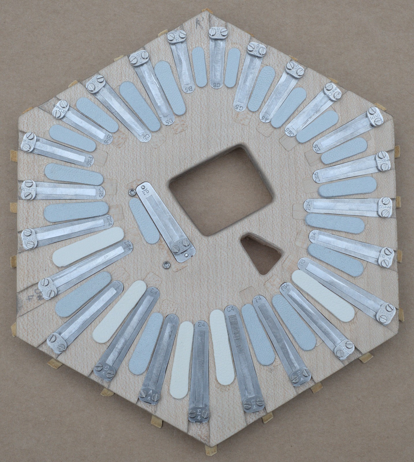
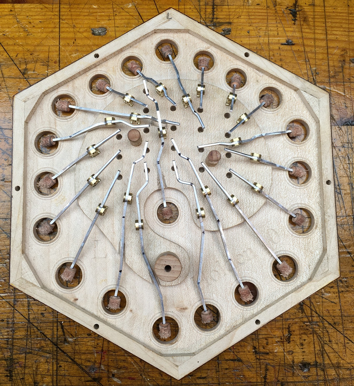
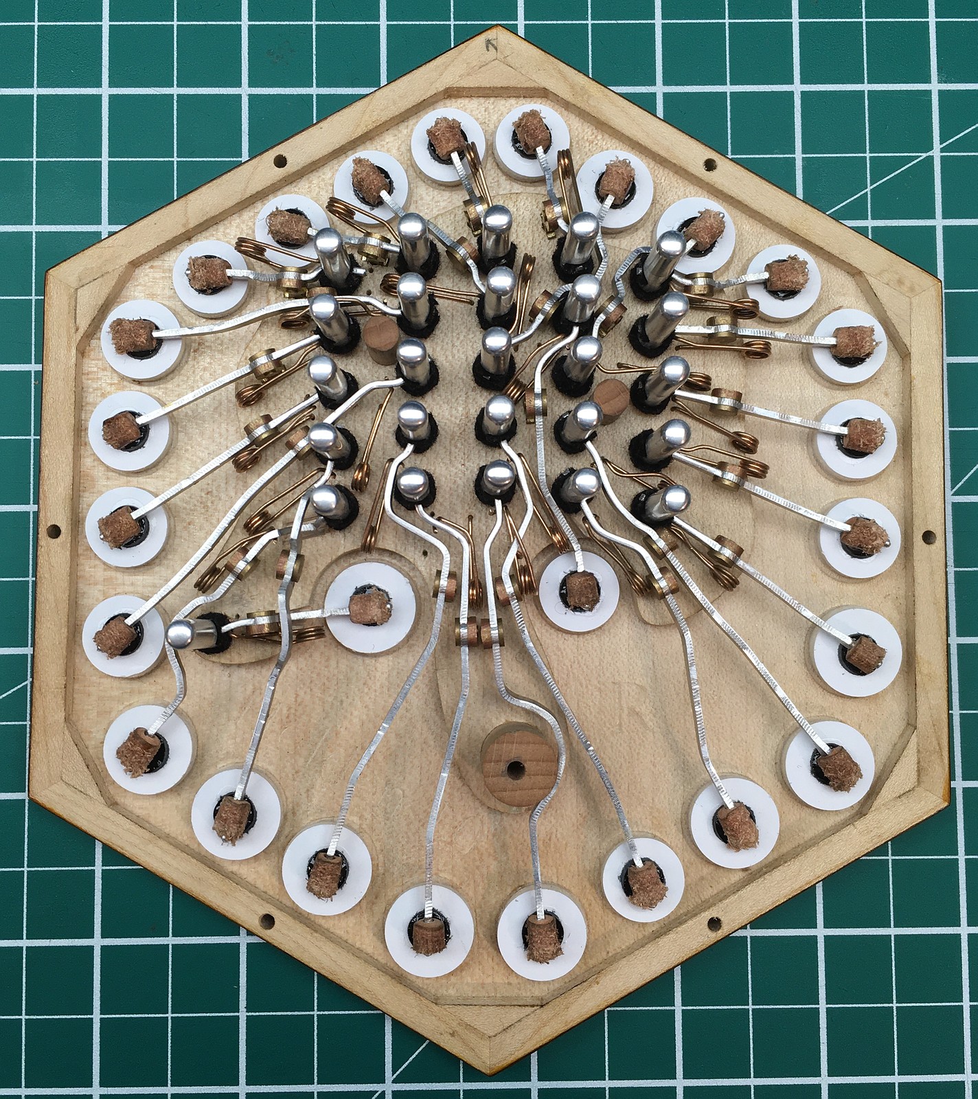
Reed Pan Improvements
I came up with some more refinements for how I make radial reed pans. The main one was that I inlaid pieces of straight-grain wood into the reed pan boards along the middle of each chamber. This solves some problems I was having caused by weak short-grain wood in the very narrow strips between the top and bottom reed frames.
First I routed out slots where the chambers were later going to be placed:
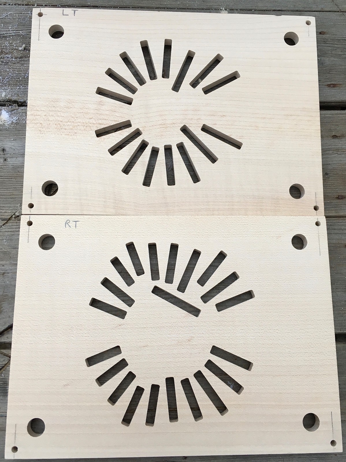
Then I glued blocks into the slots:
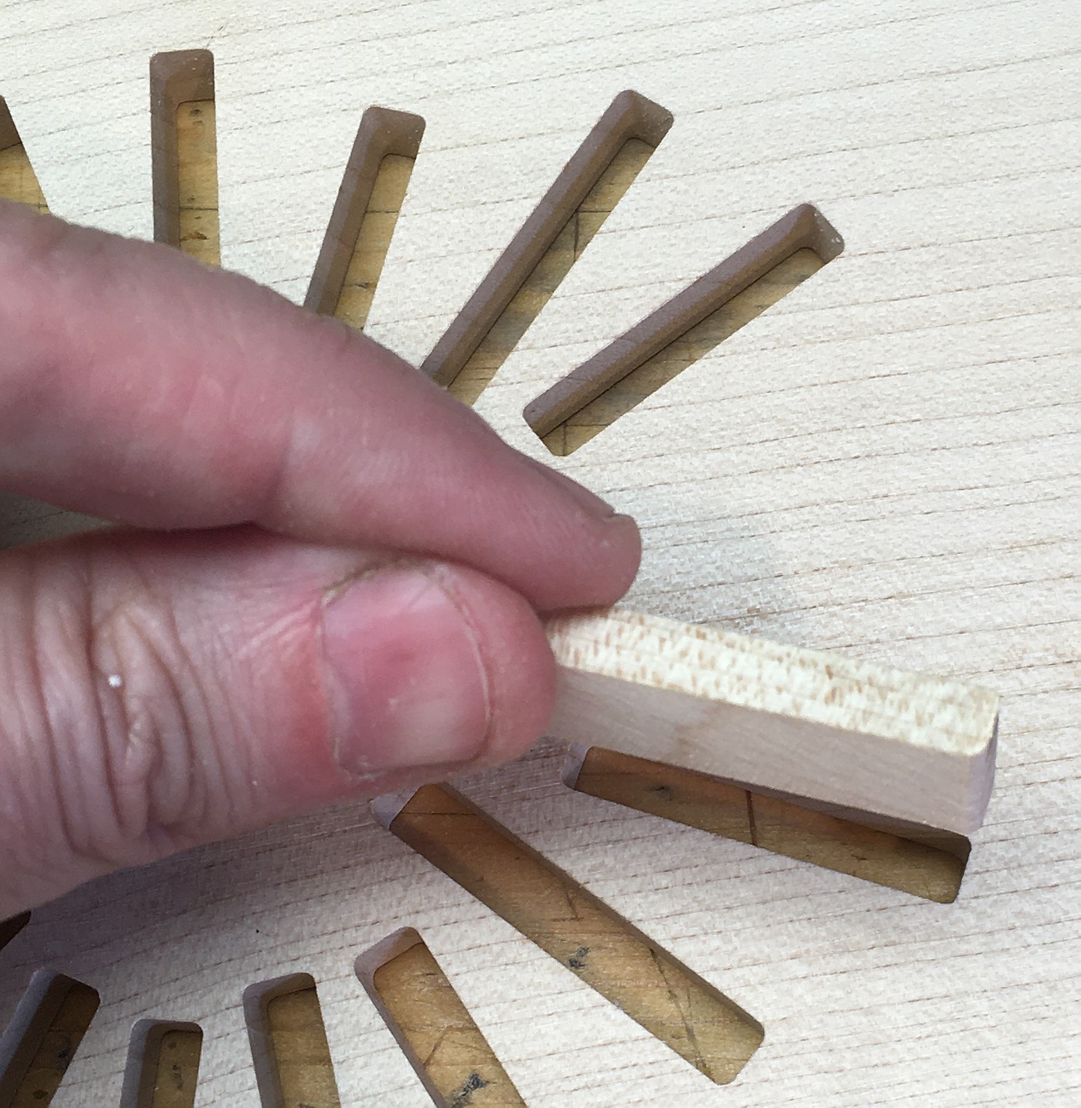
The blocks were a little thicker than the boards so they initially protruded a little bit on both sides.
I then used a drum sander to bring them down flush with the board.
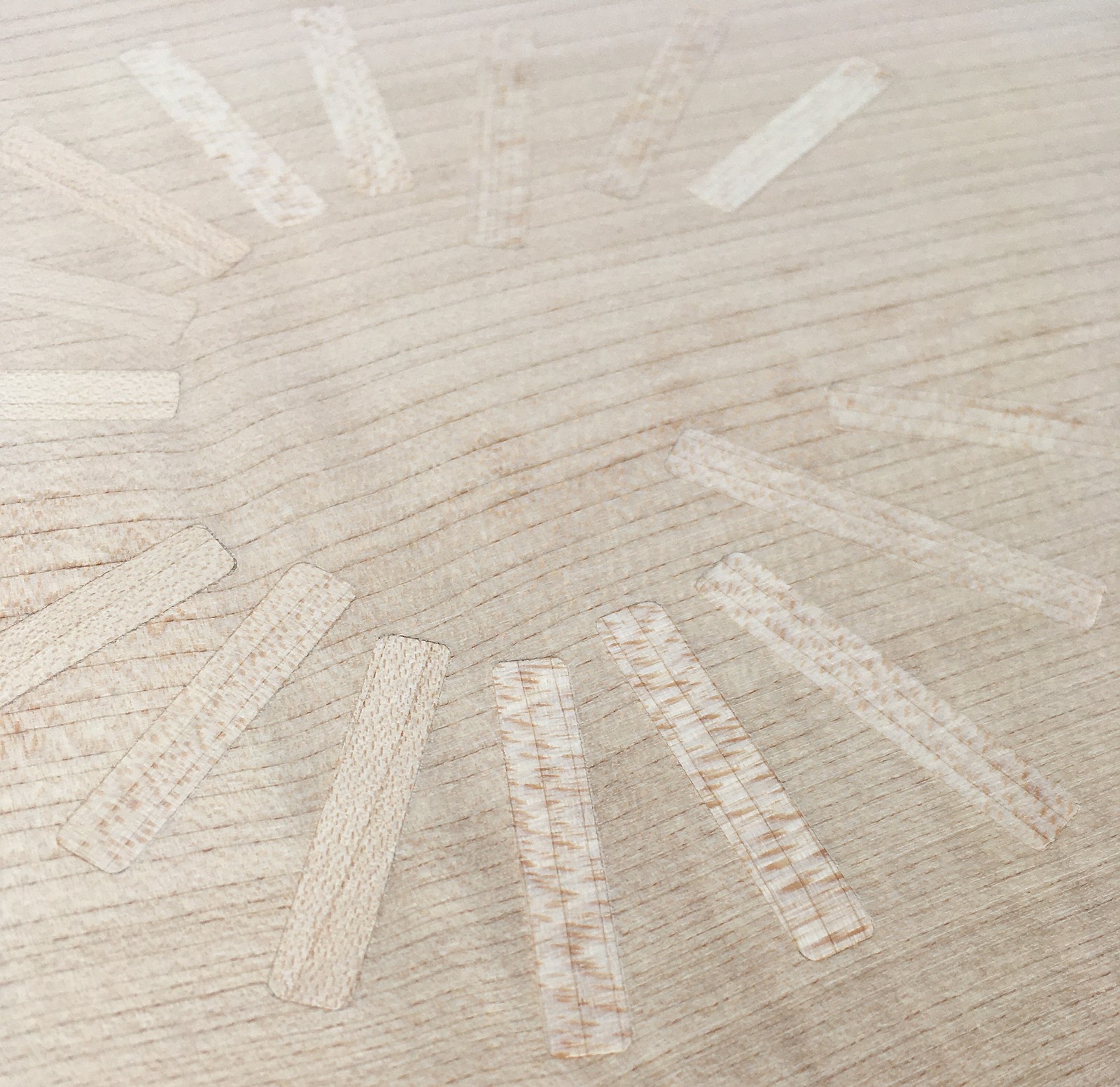
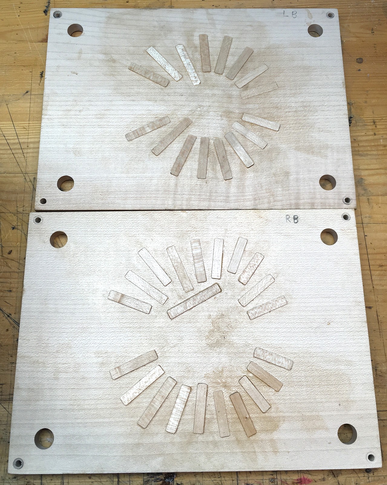
Some of the other refinements required making the wall stock even thicker, and later routing away material from both sides of each wall to form the chambers.
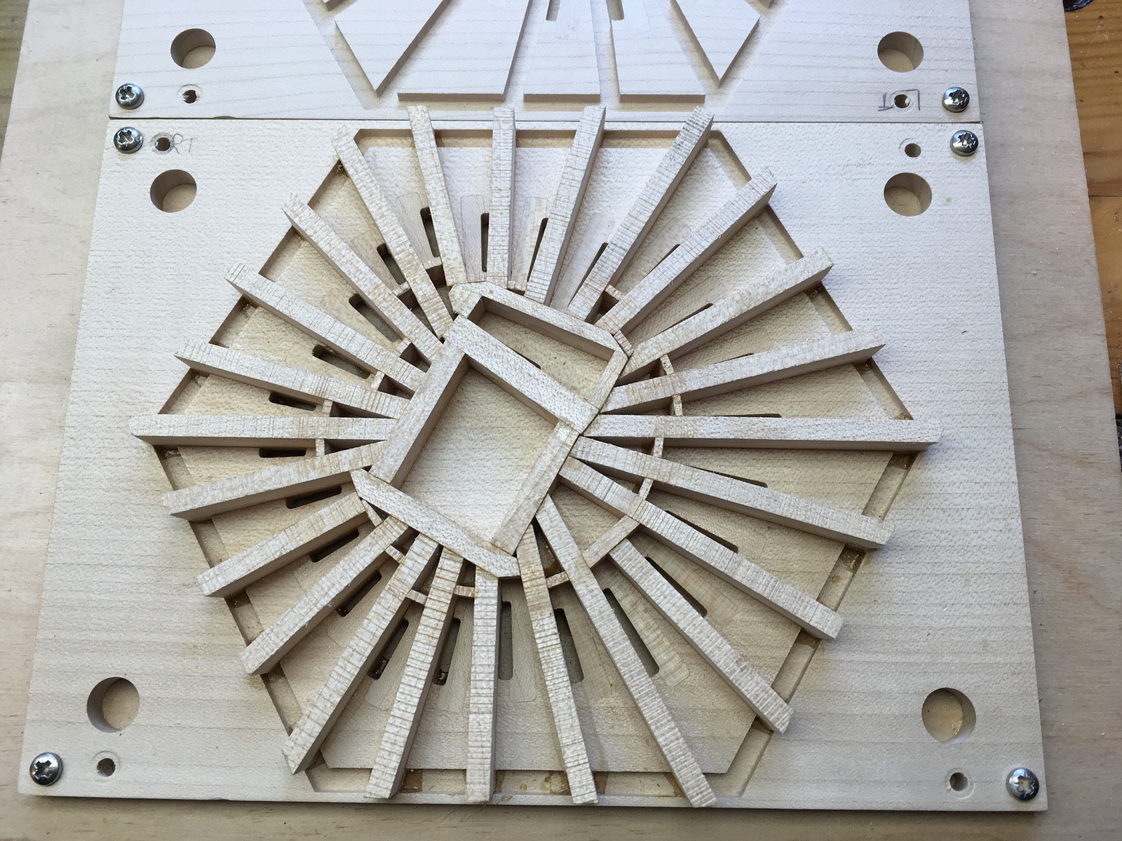
I don’t think I could make radial pans significantly denser than this.
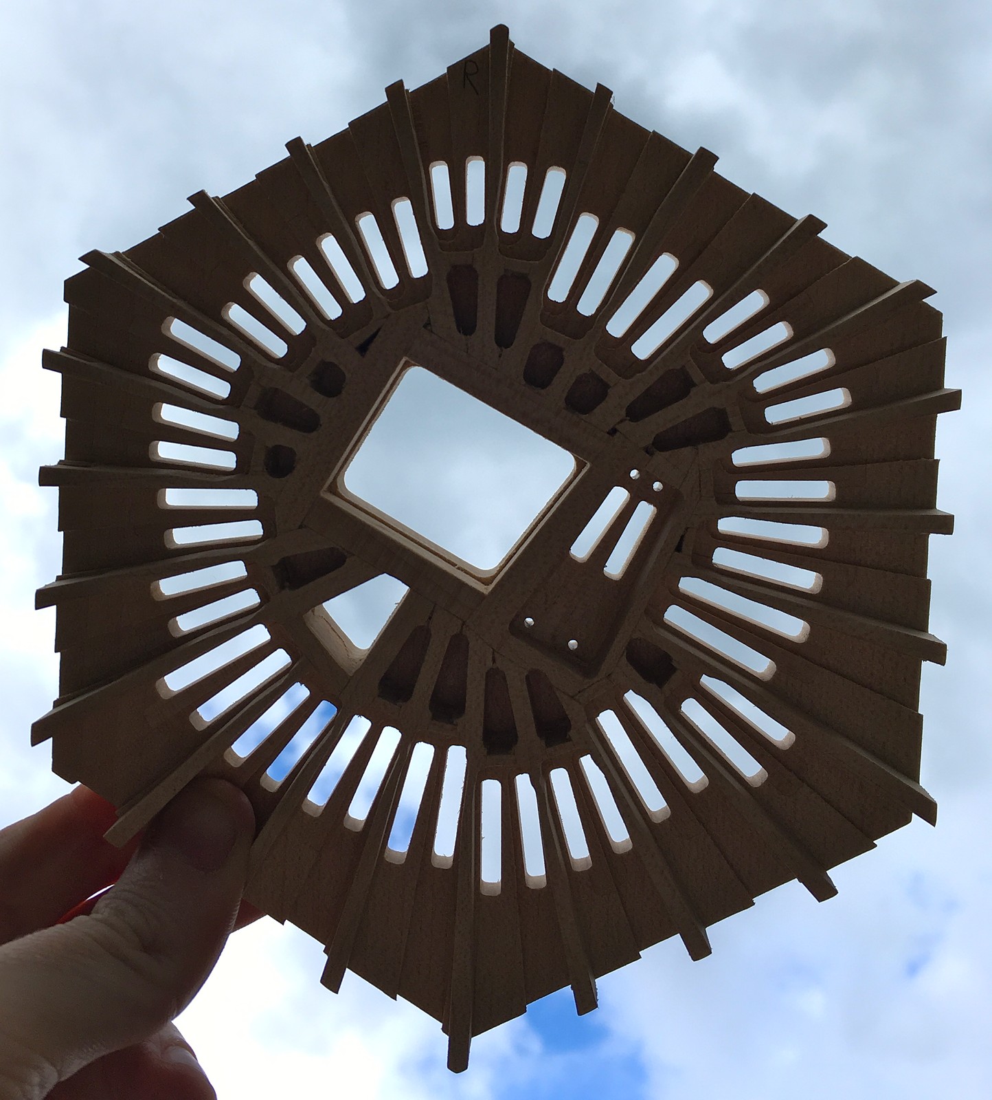
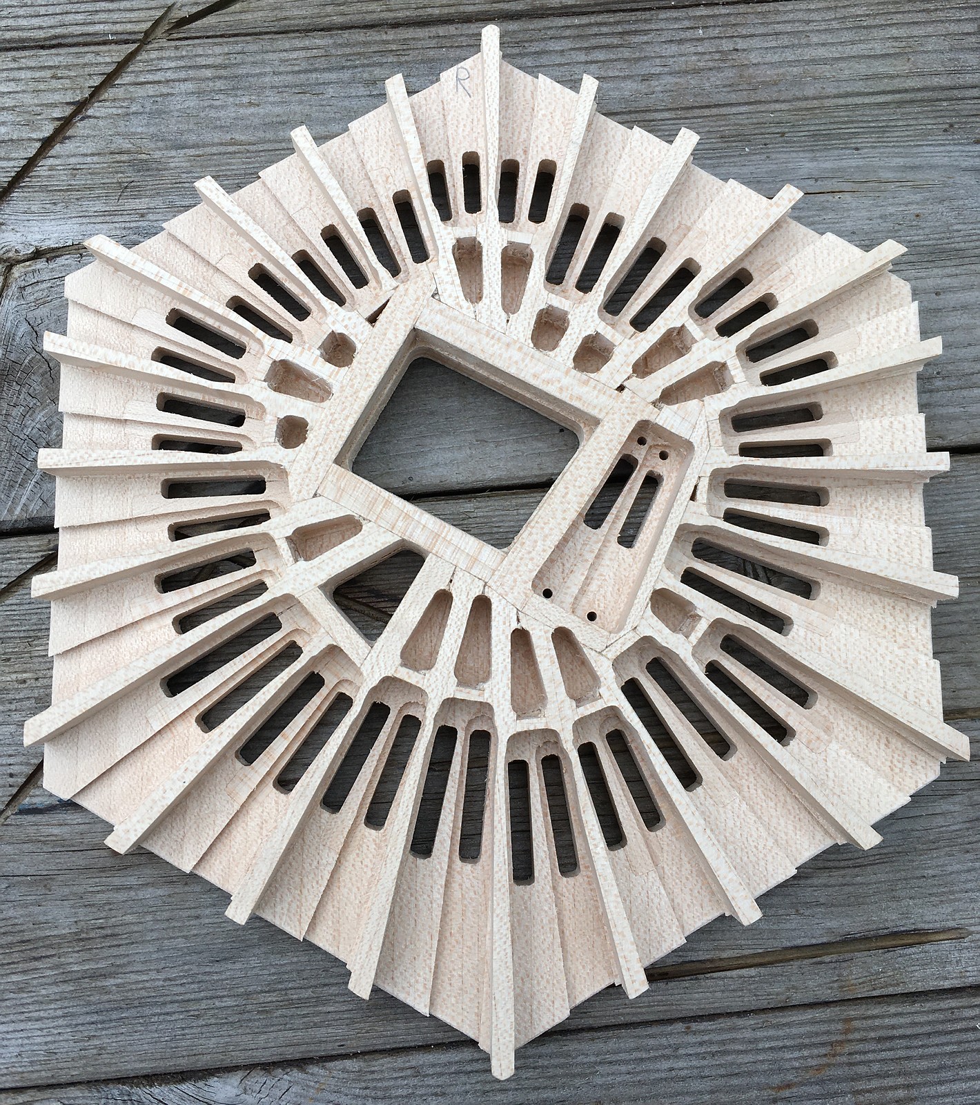
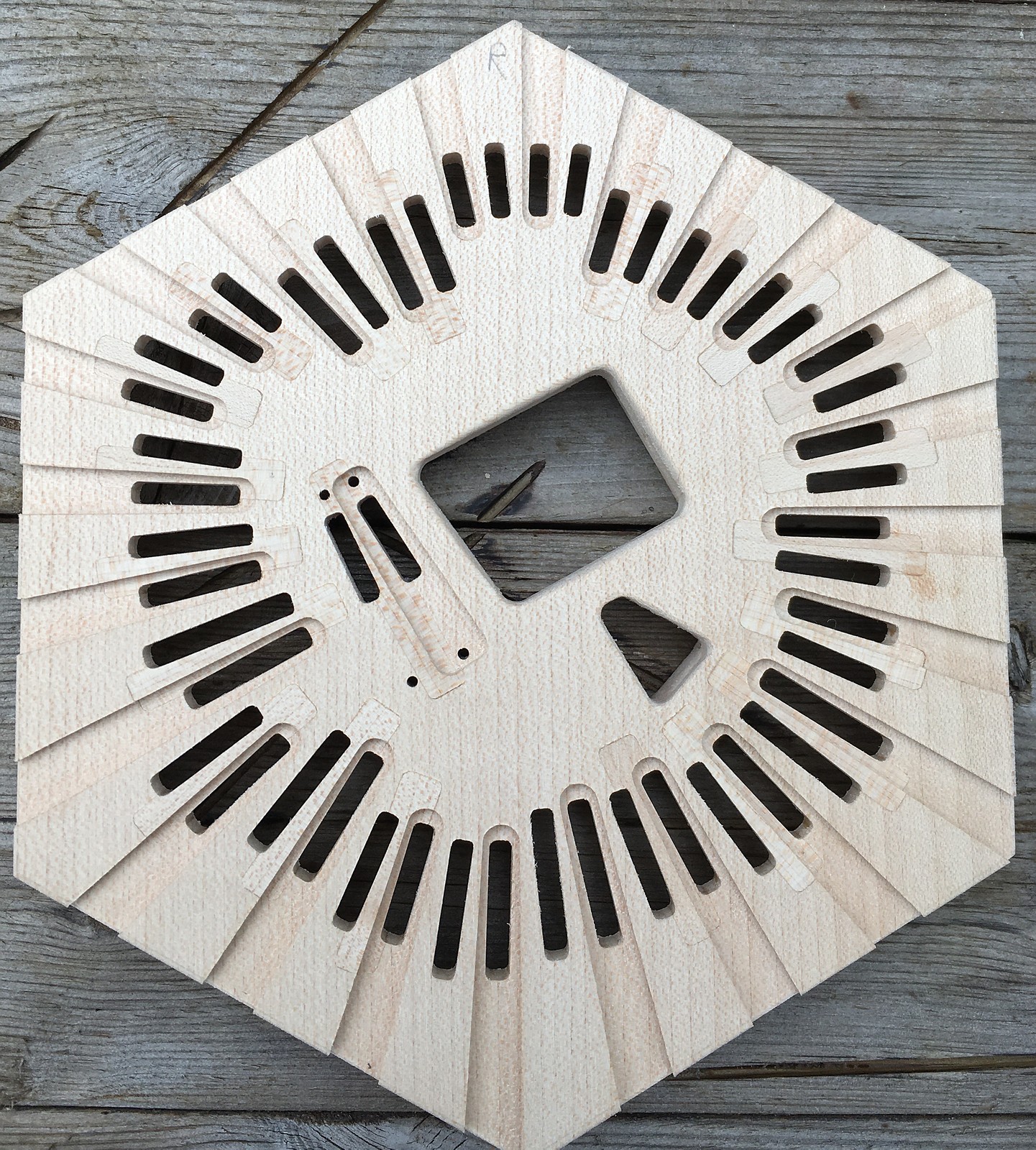
The chambers have now evolved to a fairly complex shape to satisfy the many different design constraints.
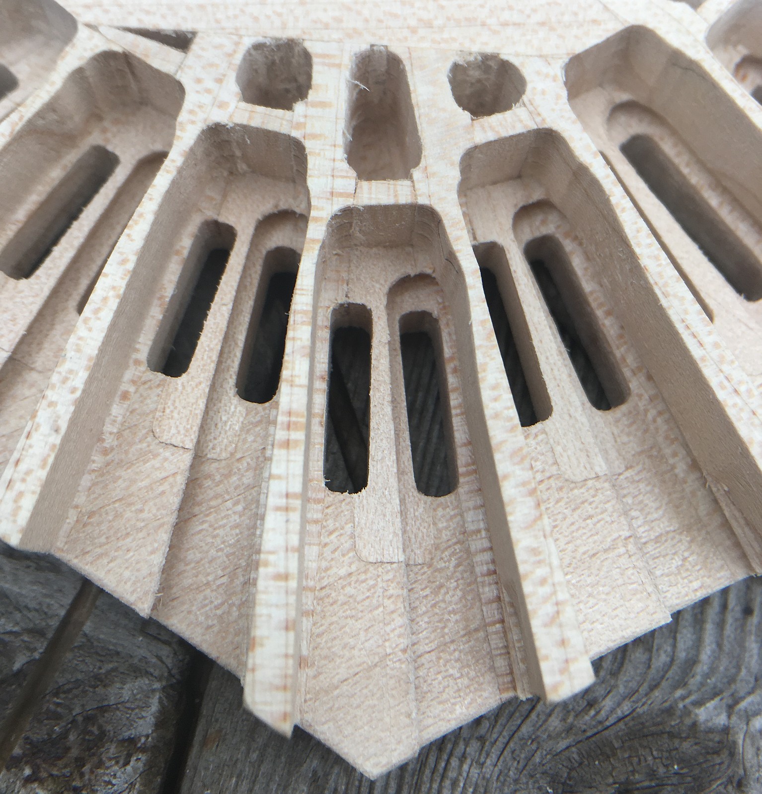
When I added the extra left hand A4 button, the only place the chamber could fit was in the centre of the pan (this modification was John’s idea).
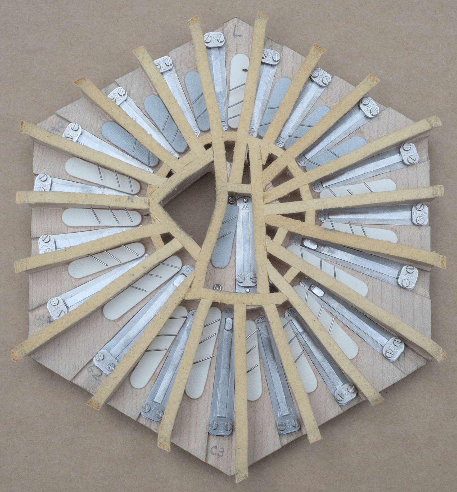
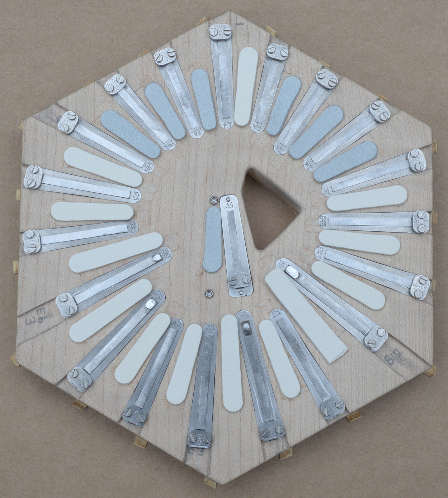
The smaller triangular opening in the middle of the right hand pan is the air passage for the air button.
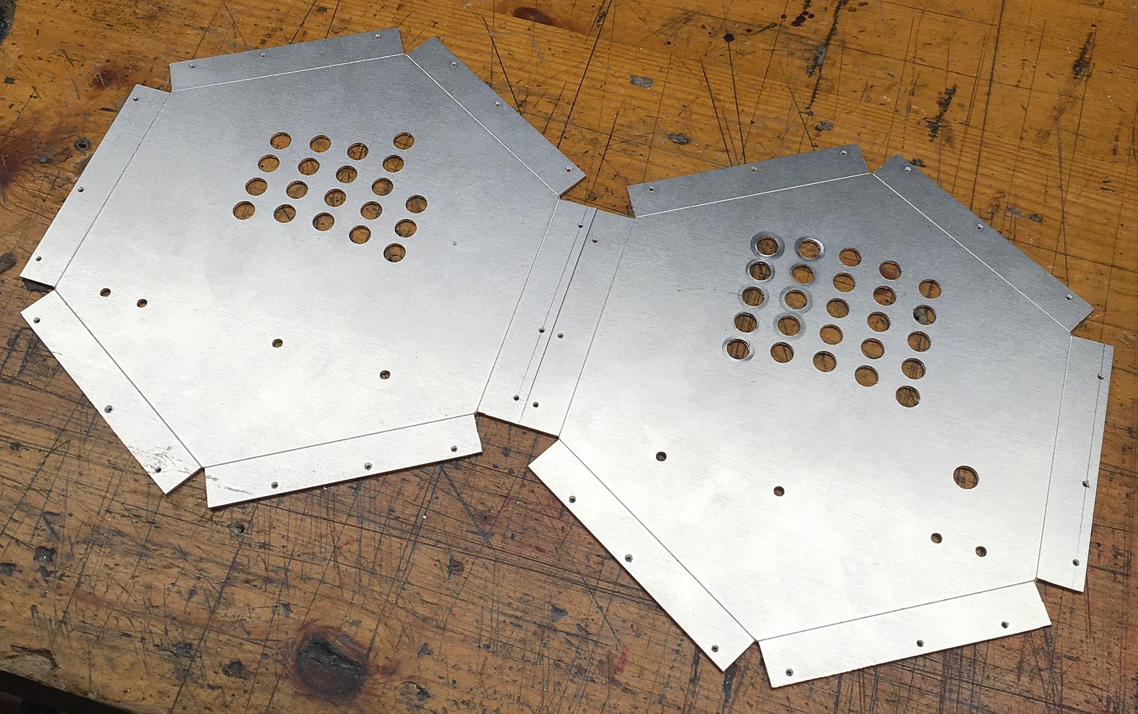
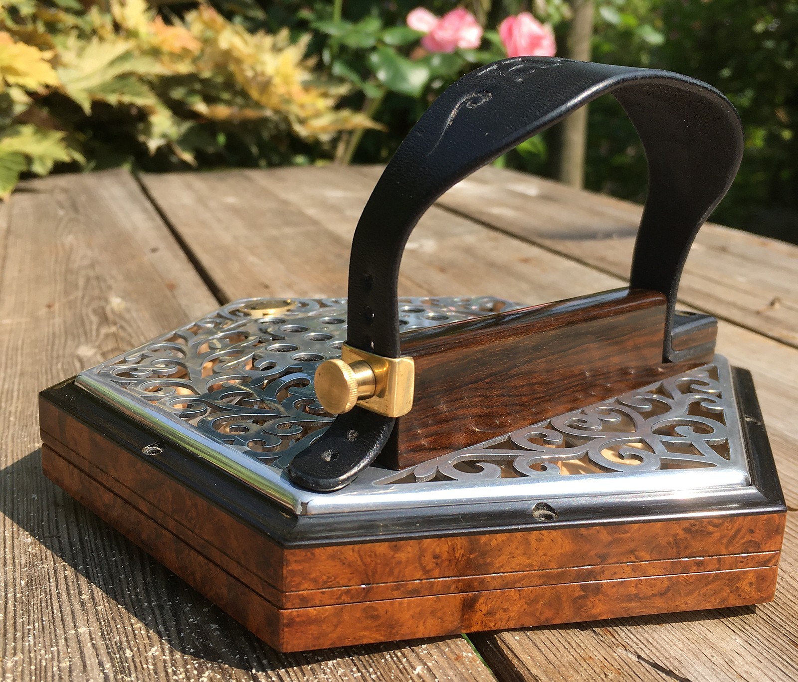
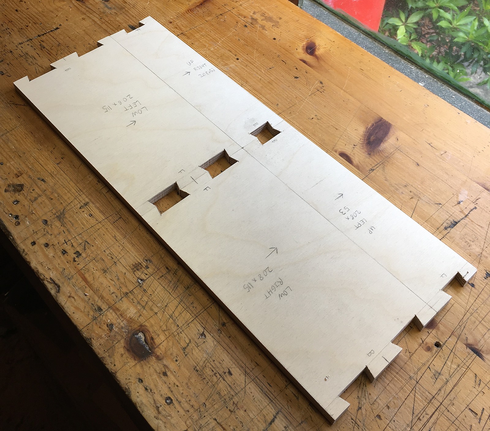
End Plates
I made the end plates from 1.2mm thick 5251-H22 aluminium. This was because John wanted it to have raised inset metal ends that were lighter than the nickel-silver I’d used previously (including the raised inset ends on No. 6), and he had previously owned a 1930s Crabb that also had raised aluminium end plates (alloy unknown), albeit with a rather simpler fretwork pattern.
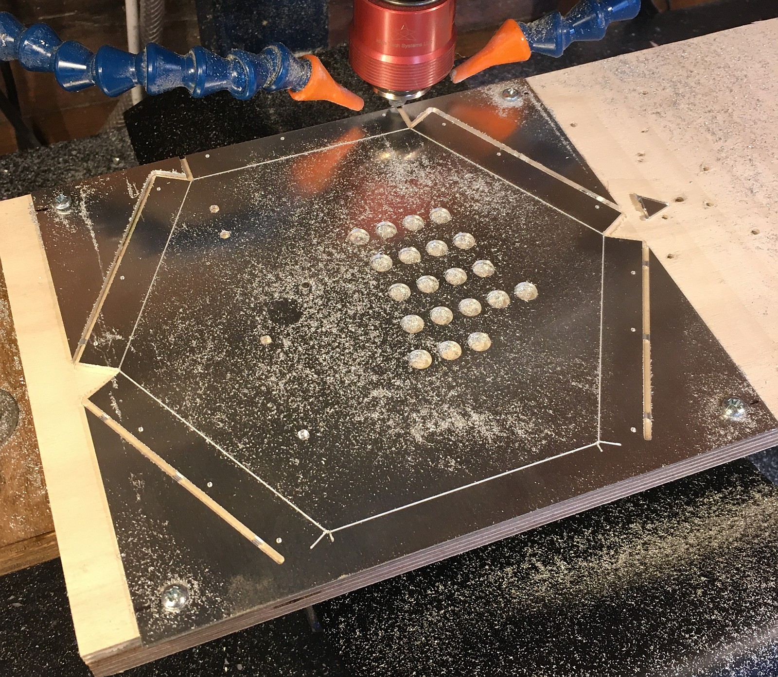
I started by using the CNC mill to bore the button holes, rough out the perimeter, and engrave bend lines – this helped to locate the critical dimensions accurately.
Next I routed a one-piece plywood male former for each side: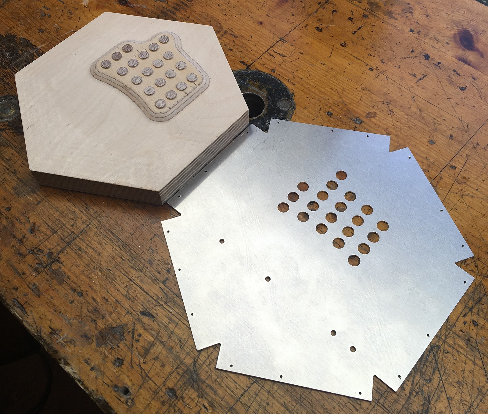
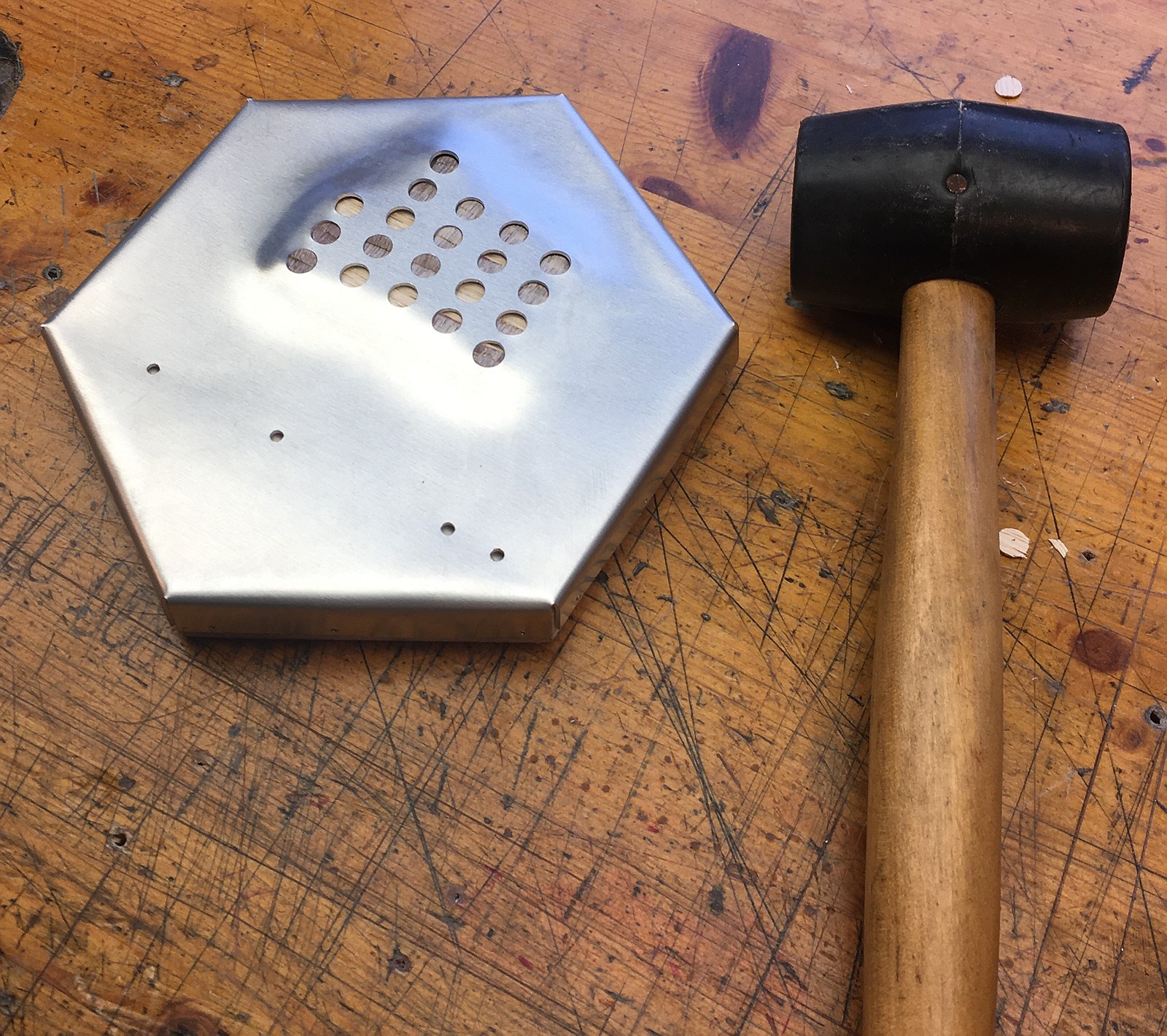
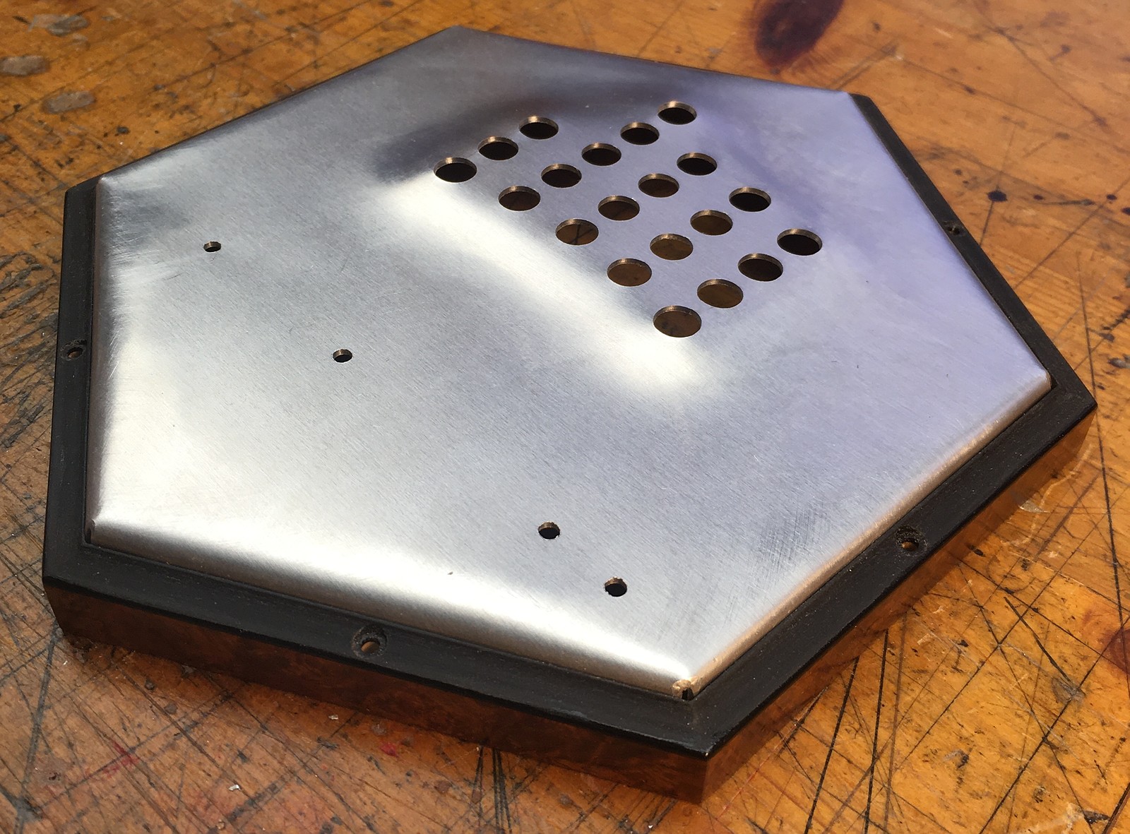
I placed the plate on the mould, using the button holes for alignment, and manually beat the metal down onto it with a rubber mallet. In hindsight, it worked but it was far more difficult and time consuming than I expected. I thought the aluminium would be soft and malleable, but it really resisted forming those compound curves in the corners of the raised area. I also had a lot of problems with bending the edges down in exactly the right place and getting straight fold lines. In hindsight, although I made it work, I wouldn’t do it this way again.
It was a struggle to get the plates to fit snugly into the action boxes, but the end result looks quite neat.
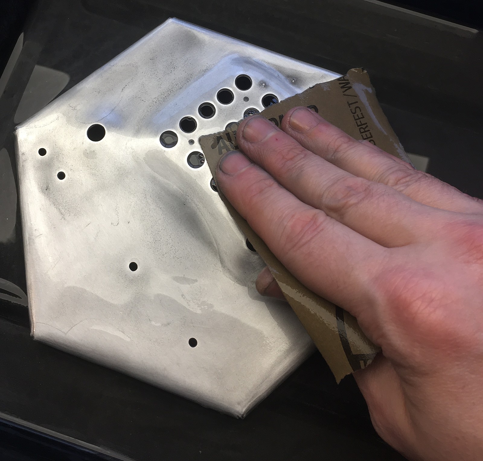
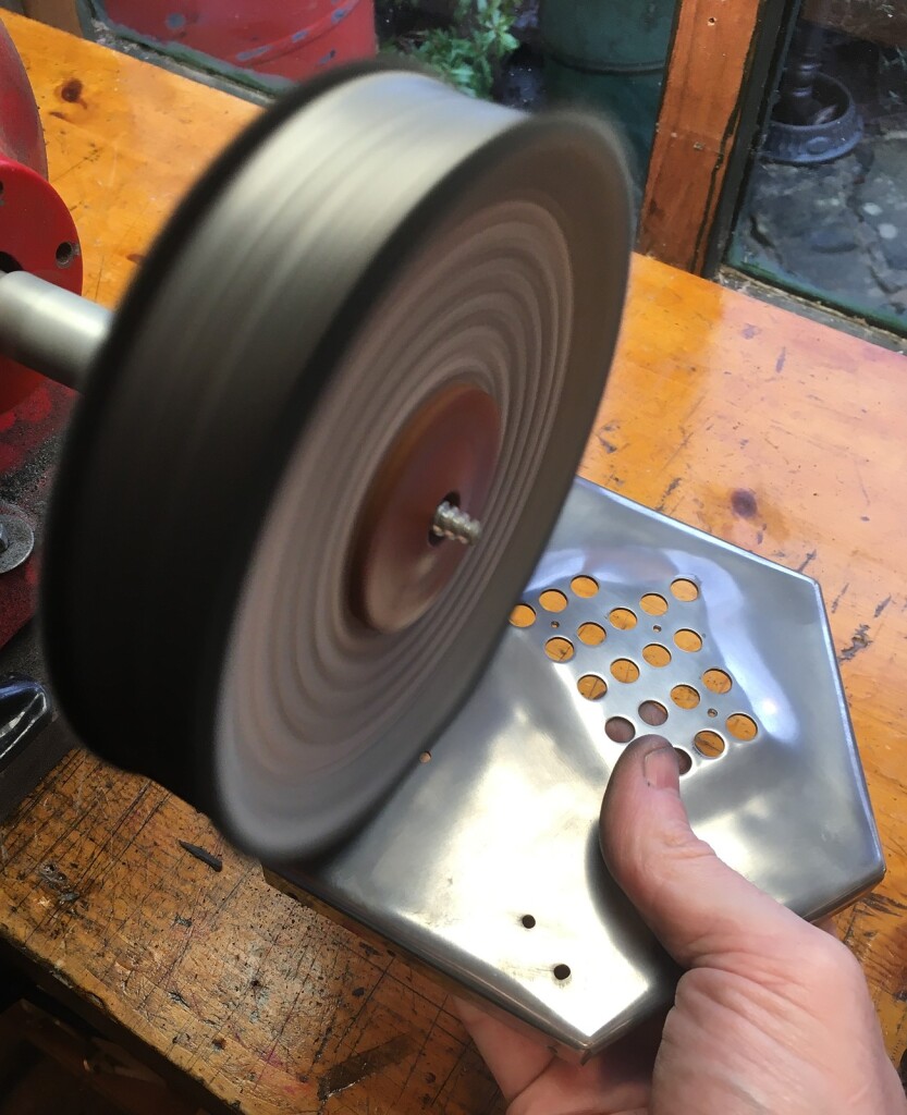
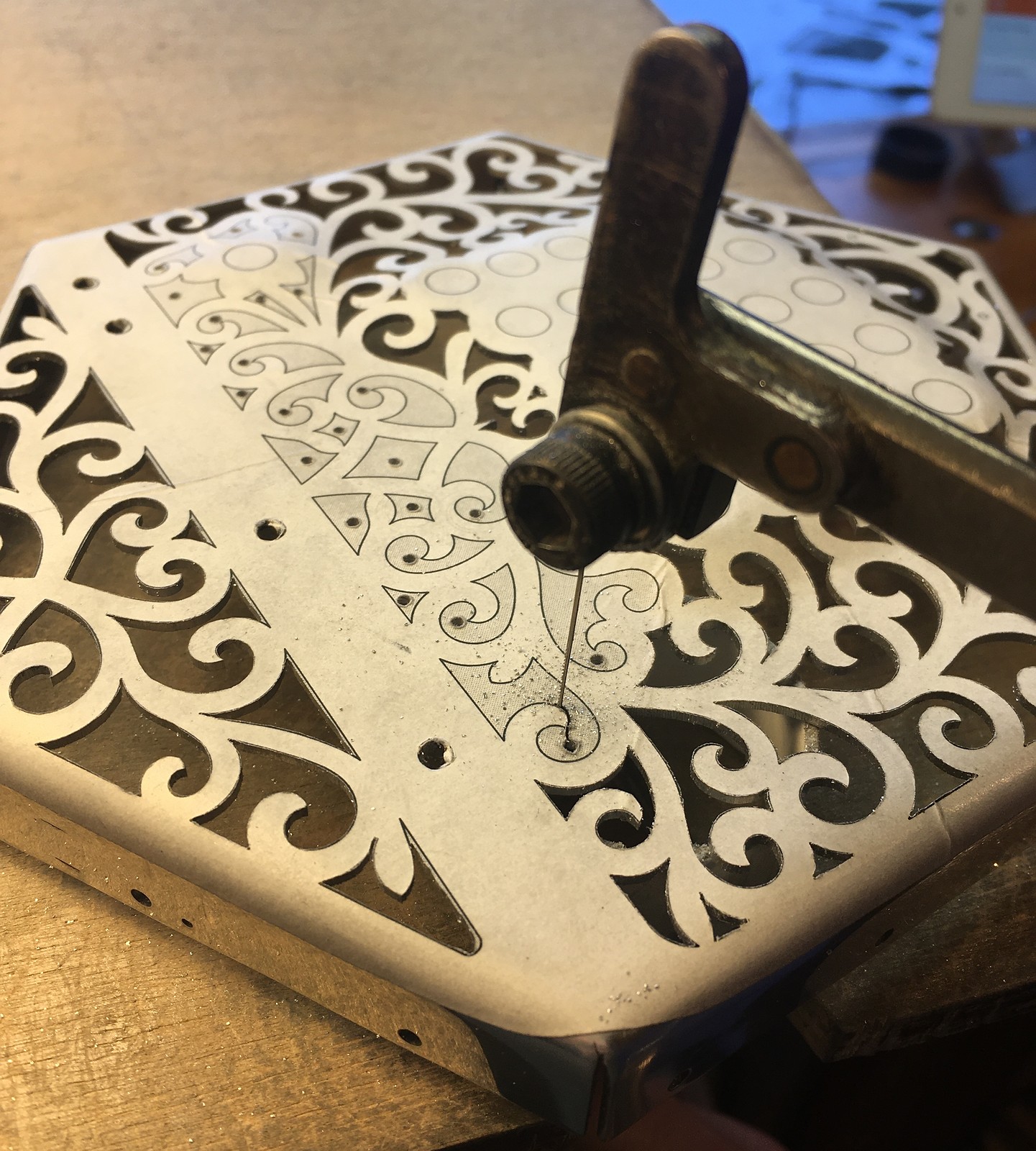
I wet sanded and polished the plates to a bright shine before cutting out the fretwork.
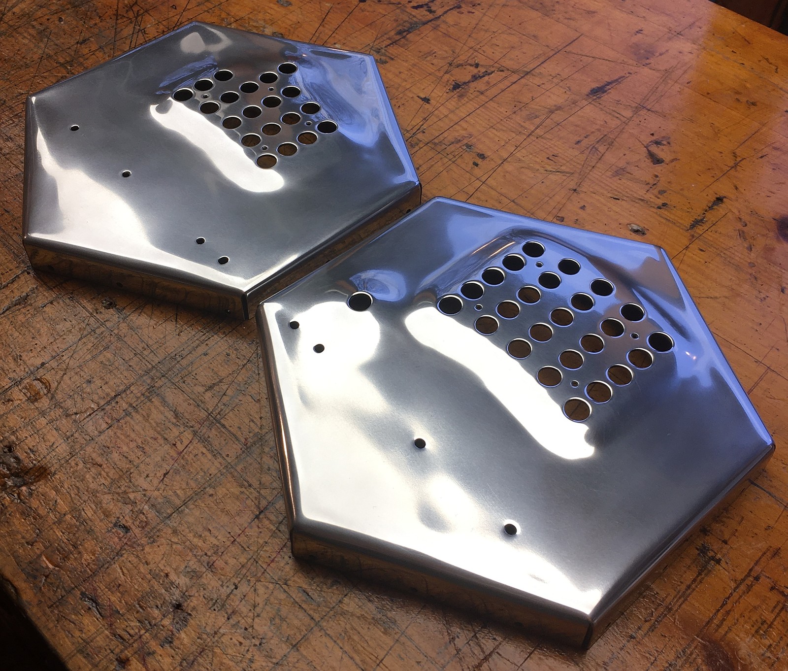
The design is only slightly modified from No. 4.

The aluminium was pretty easy to cut as it is quite a bit softer than nickel silver. Because I had already folded down the edges, I used a small offcut of plastic tube to support the end plate beneath the area I was cutting.
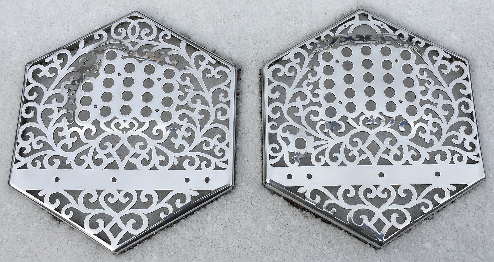
When freshly polished they shone like mirrors. This dulls down a little over time, but it doesn’t seem to suffer from the sort of tarnish you get with brass or even nickel silver, because once there is a thin layer of oxide on the surface, it forms a protective barrier that prevents it getting any worse.
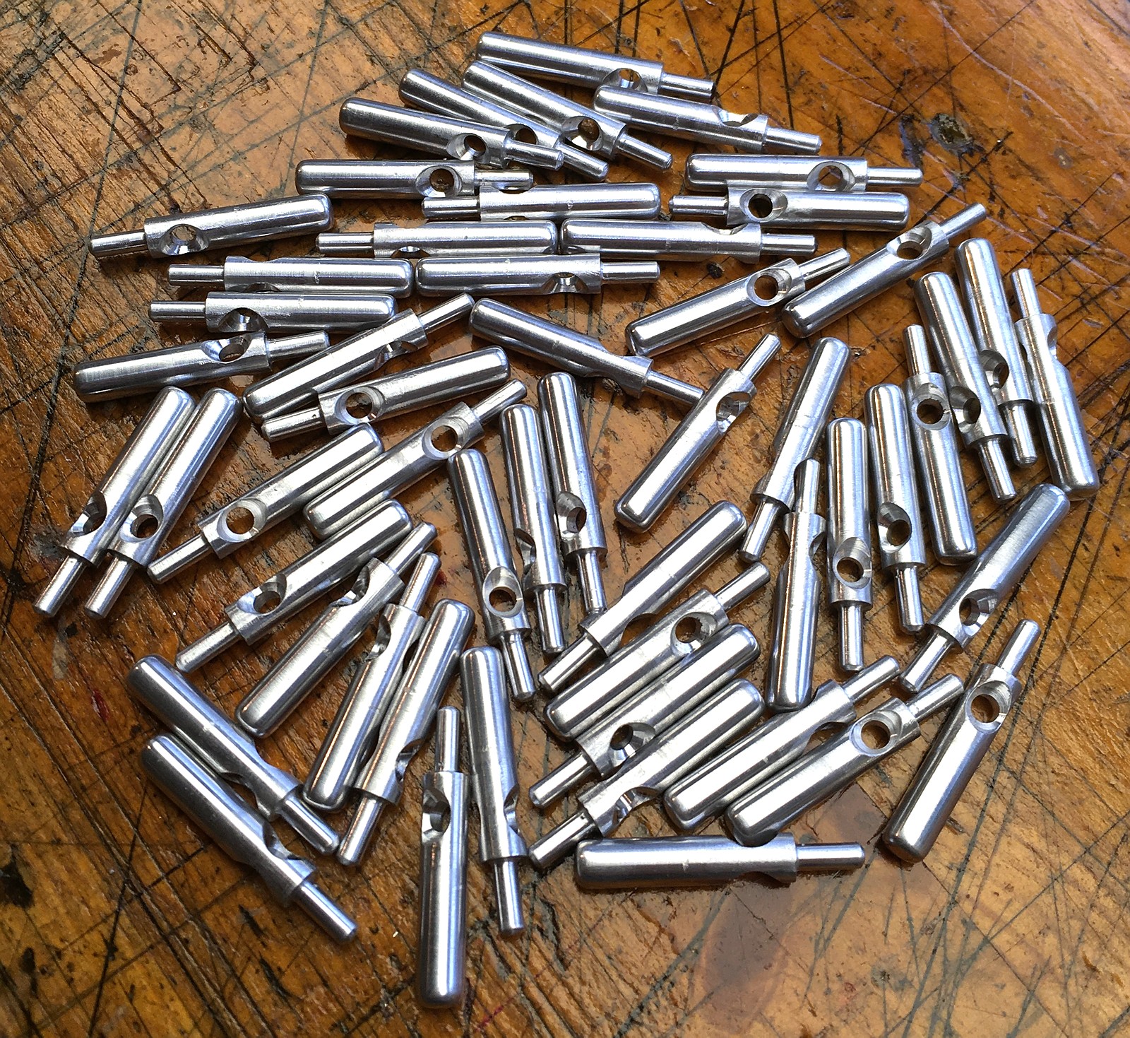
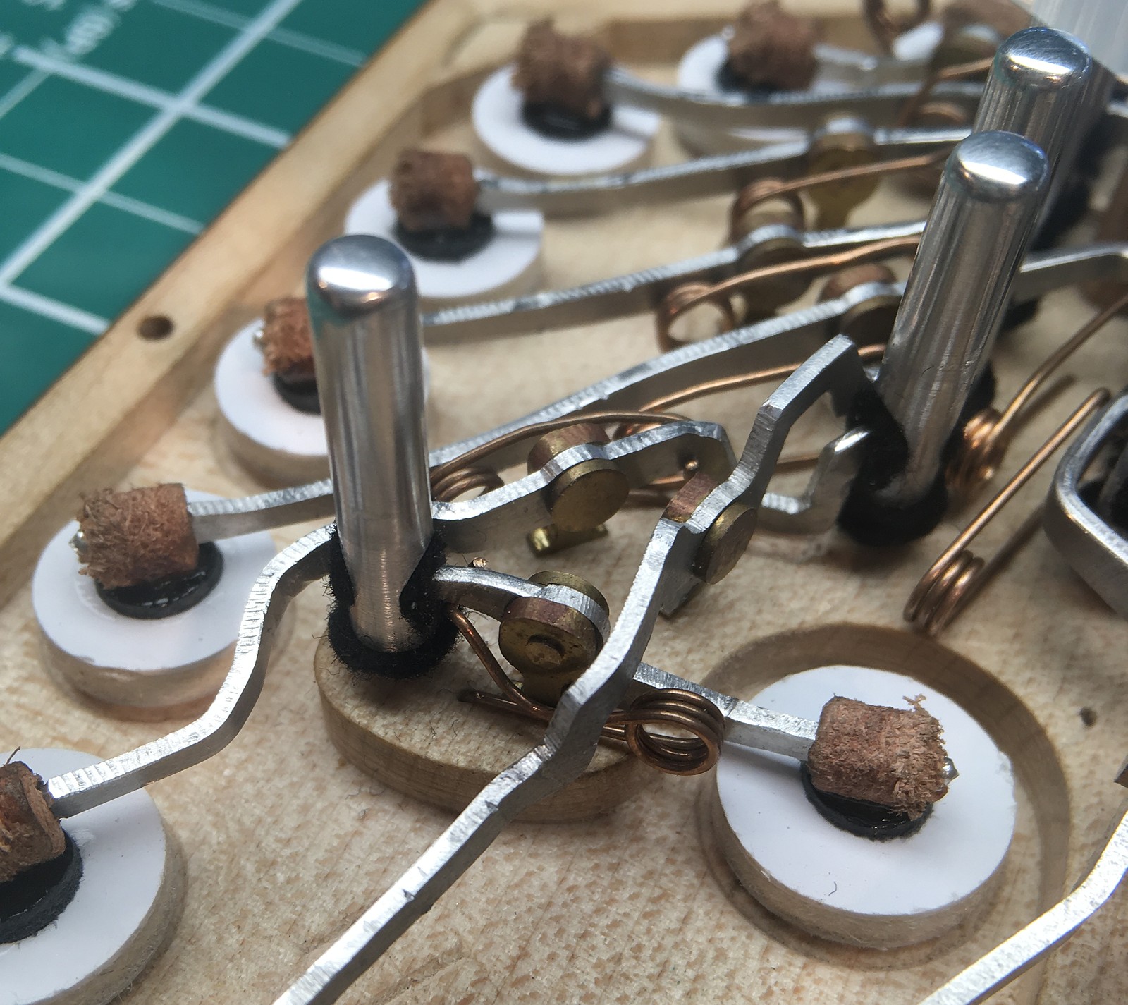
Action
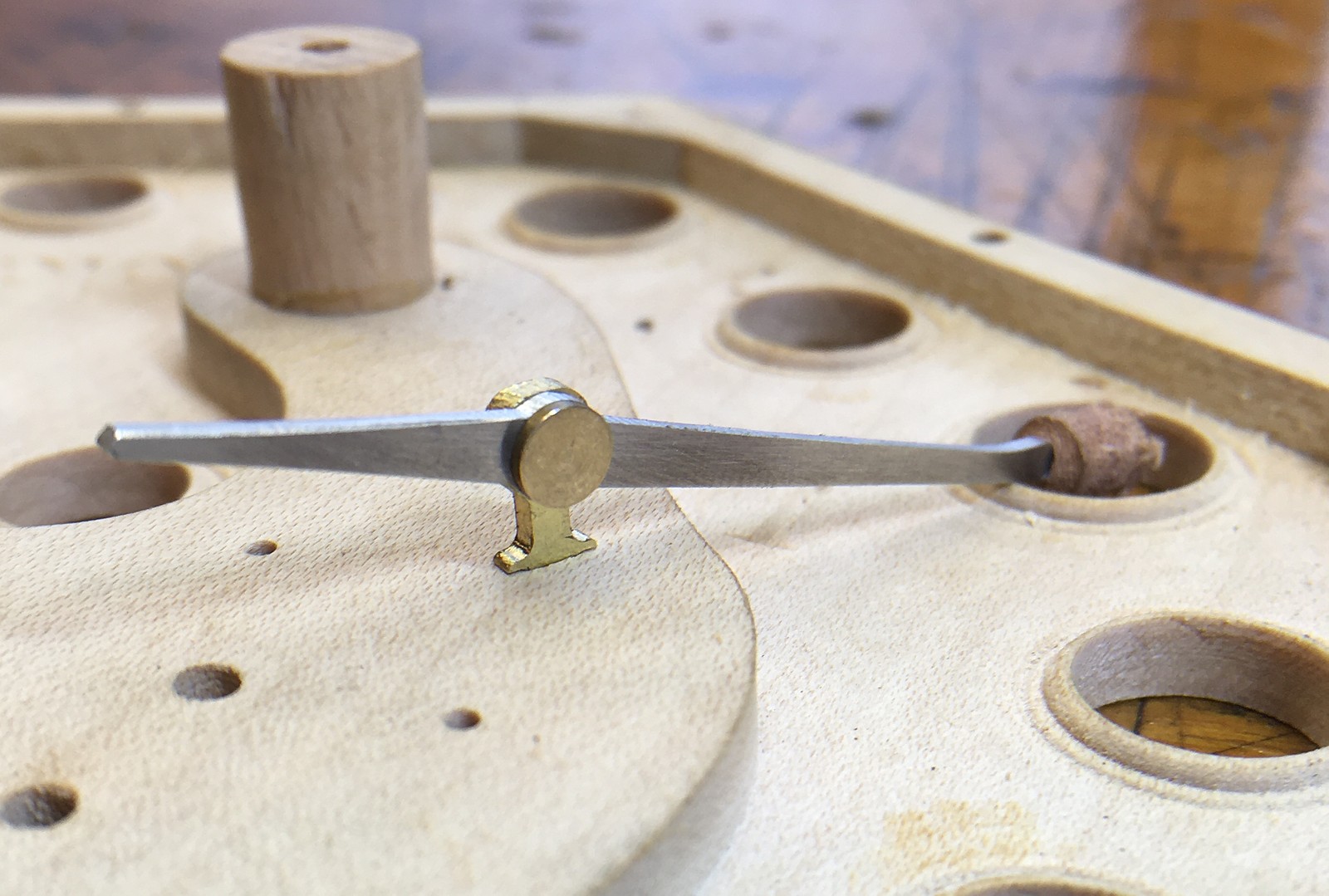
I also used exactly the same aluminium sheet to make the action levers, for weight saving reasons. The posts and pivots are still made from brass because you can suffer from galling (high friction and premature wear) if you have two aluminium parts rubbing against each other. I increased the pivot diameter to 2.2mm, so there is a decent amount of bearing surface and I don’t expect them to wear quickly. The assembled action boards felt significantly lighter than they usually do with brass levers, and I wouldn’t hesitate to use aluminium levers again in an instrument when the client is concerned about minimising weight. Arguably they may be slightly quicker to open and close too, due to reduced inertia.
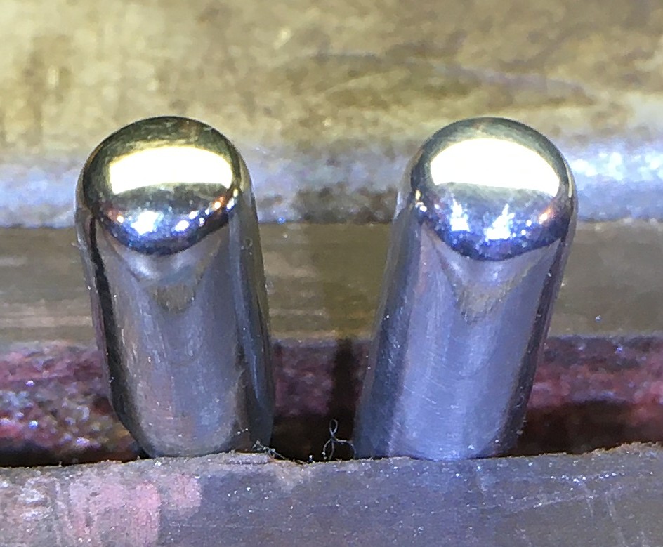
We also decided to turn the buttons from solid aluminium. I think their weight is fairly close to my standard hollow nickel silver buttons, but the main advantage is that the colour of the metal matches that of the end plates. This picture shows one of my pressed nickel silver caps on the left and a solid aluminium button on the right. I went to some effort to match the top profile, which I think is quite comfortable on the fingertips. You can see that the nickel silver has more of a yellowish tint that might have looked a little odd next to the cooler white of the aluminium plates.
I was quite pleased with how the aluminium buttons turned out. They were significantly quicker to make than capped buttons, I can make them in any diameter the client wants, and I didn’t notice any issues with tarnishing (John’s previous Crabb instrument had aluminium buttons that were still shiny after 80+ years). The worst part of making them was deburring the cross-holes.
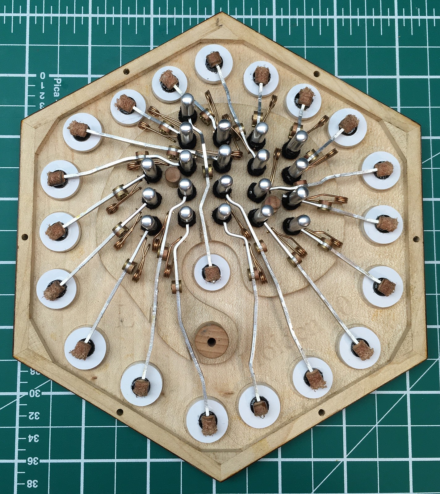
No. 10 and No. 4 both have an air button in the Anglo-style right thumb position (albeit with a smaller diameter pad due to space constraints). This leads to some slightly tricky action lever routing.
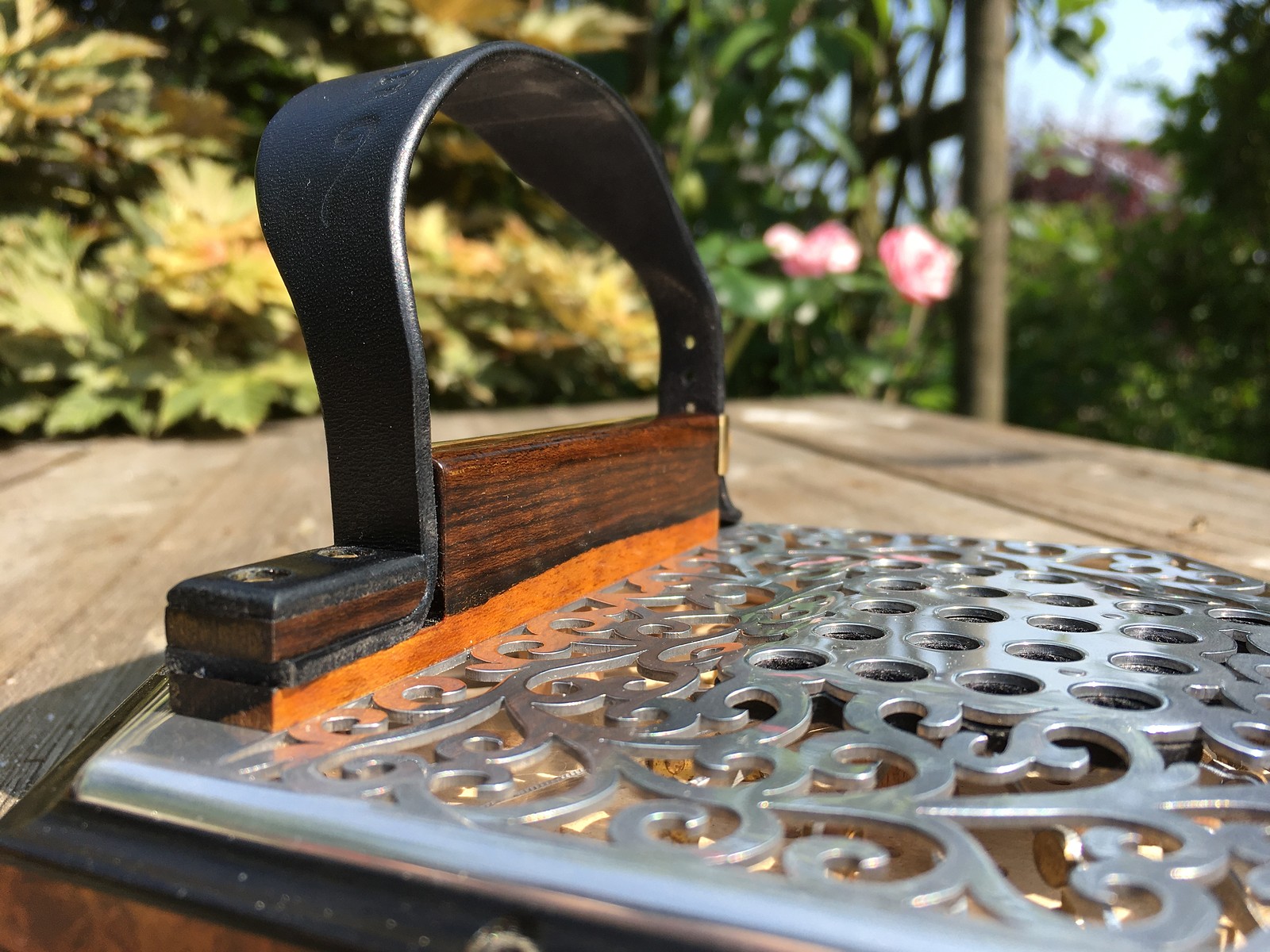
Exterior Wood
The action box veneer was amboyna burl, and the hand rails were lightly figured ziricote, incorporating a stripe of lighter coloured sapwood on the side facing the keyboard. We left the fixtures, screws, and maker’s plates as plain yellow brass as a deliberate contrast to the white metal of the end plates and buttons.
Bellows
We decreased the number of bellows folds from seven in No. 4 to six in No. 10, because in the meantime I have found ways to increase the capacity per fold, such that the two instruments hold about the same amount of air but No. 10’s bellows are slightly smaller and lighter. They have my Pictish key pattern bellows papers printed in gold on black.
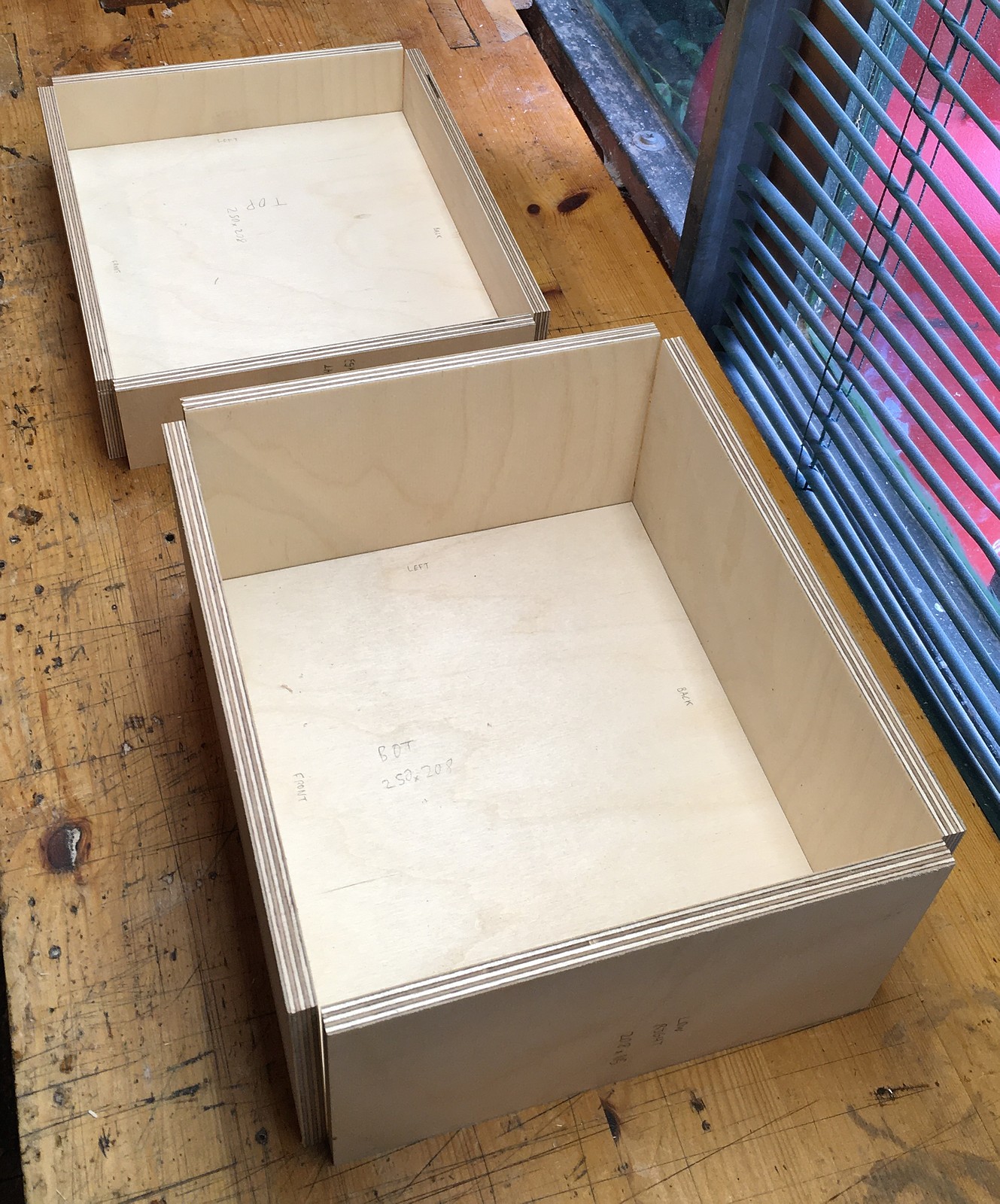
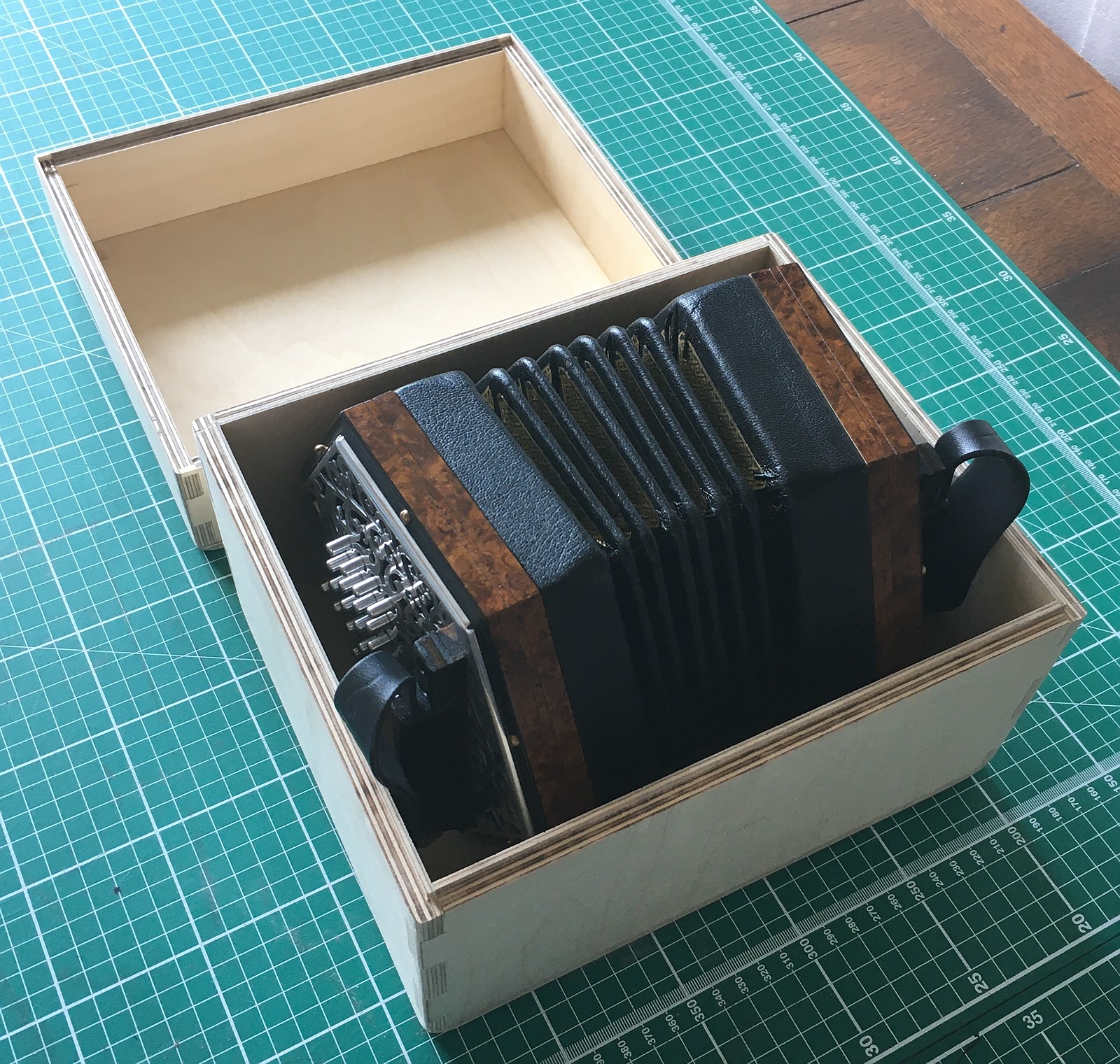
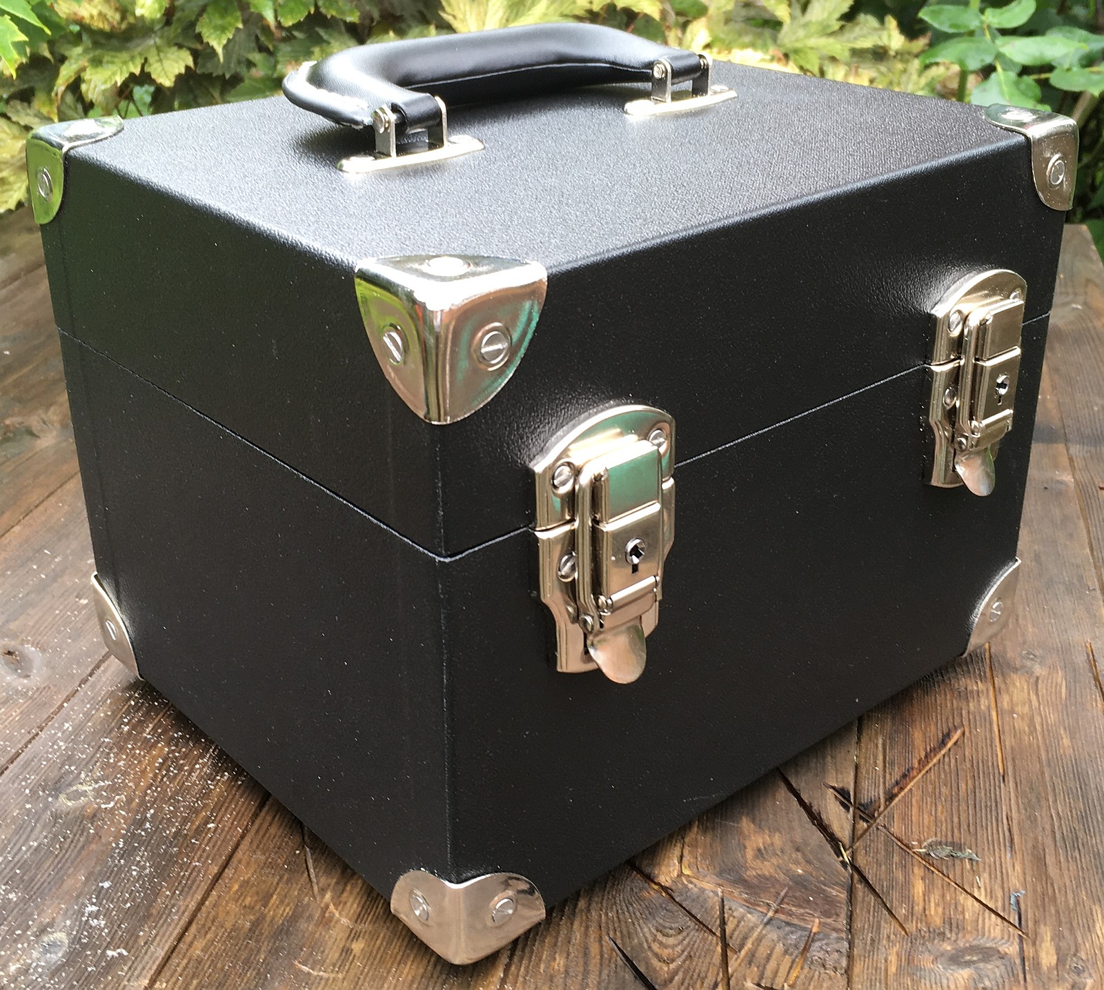
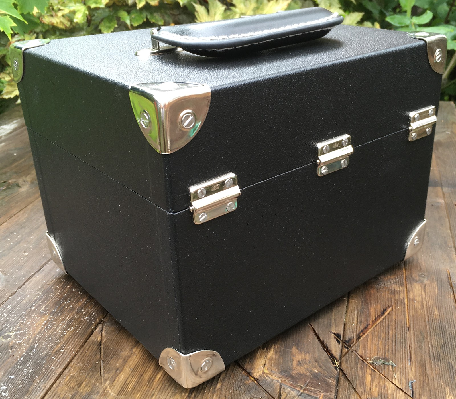
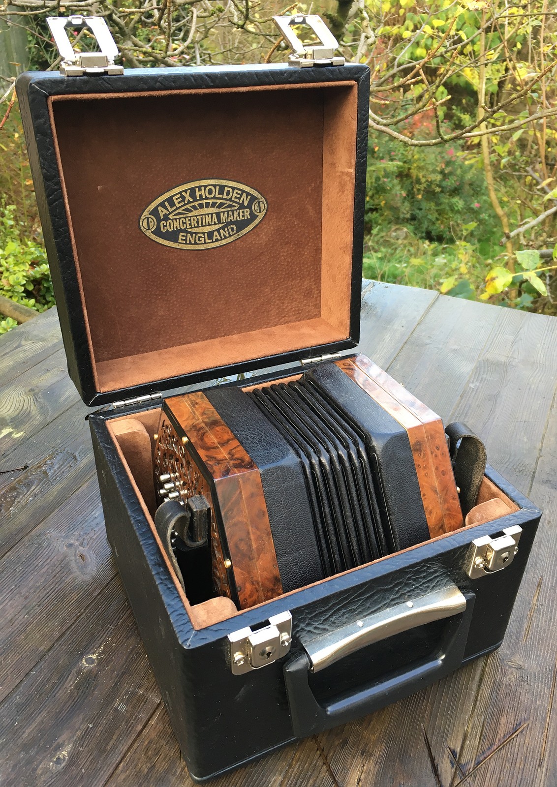
Deluxe Hard Case
After seeing the deluxe case I made for No. 9, John asked me to make something similar for No. 10, with a few differences in the details.
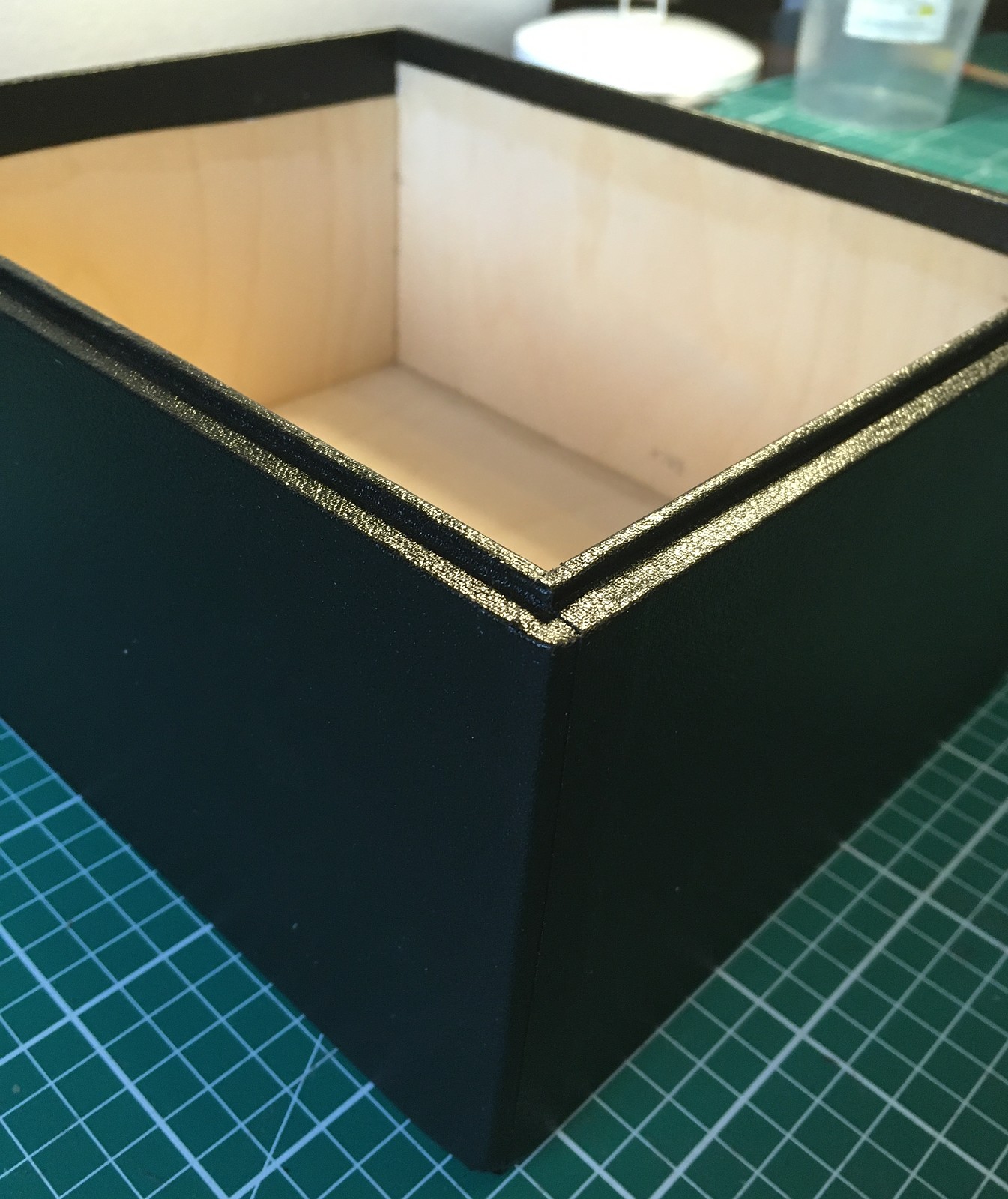
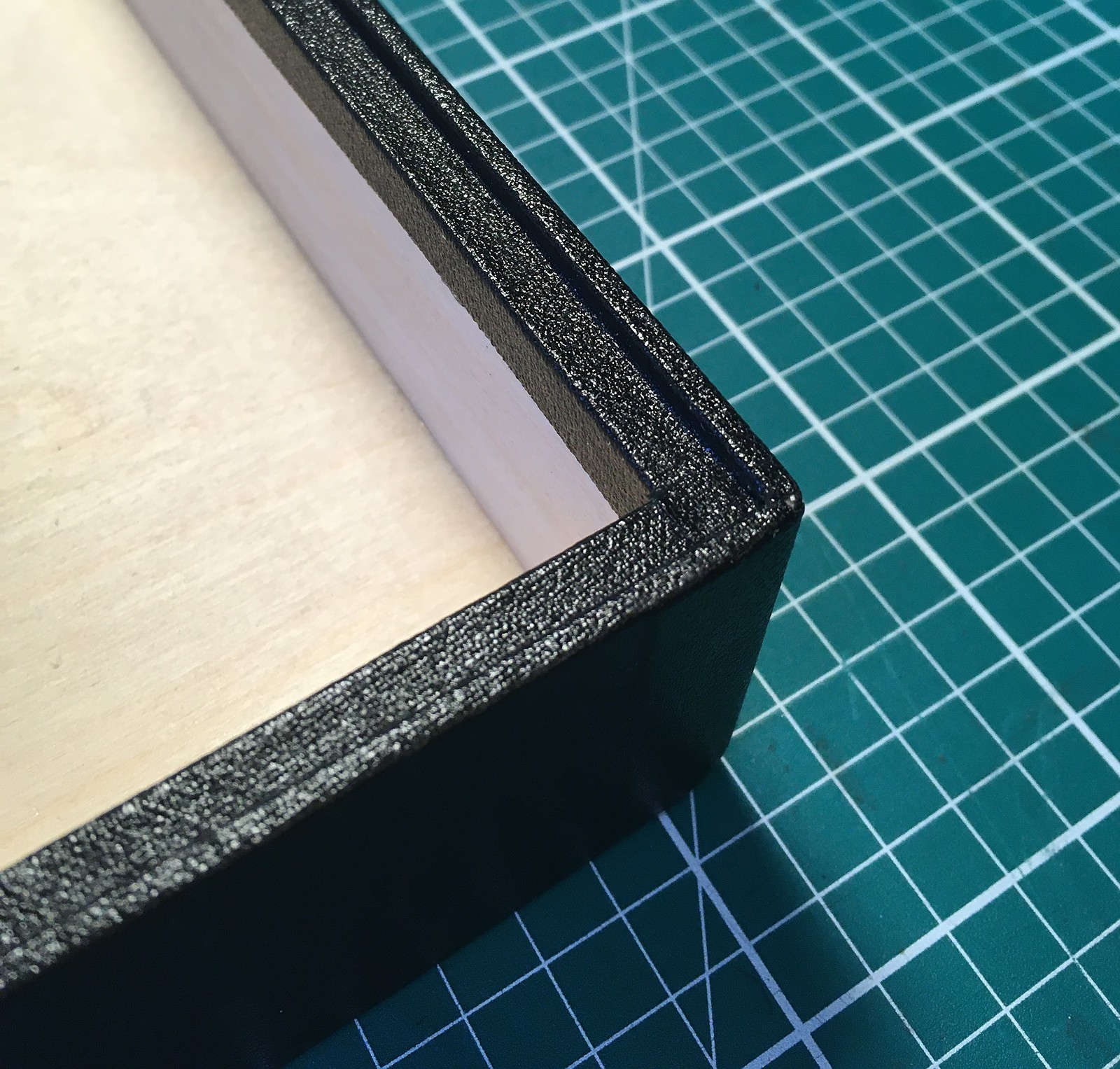
These stepped corners are the trickiest part to cover. I think I managed to do a neat job on this one.
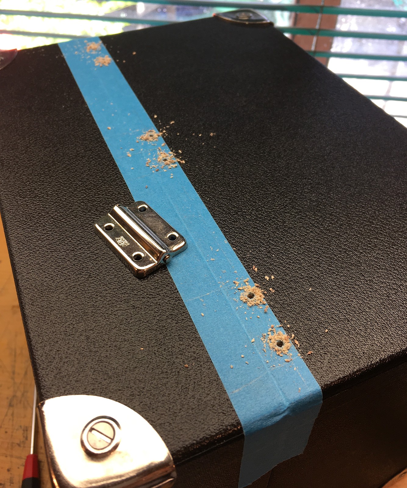
I have a limited supply of these unusual nickel plated hinges available, because I bought a box of new old stock on eBay and I believe the company that manufactured them no longer exists. Because they are quite small I felt it would be sturdier and more reliable if I fitted three of them.
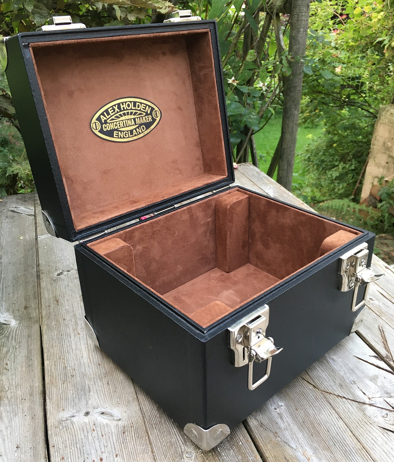
I didn’t use any internal padding, in order to reduce the overall size of the case slightly.
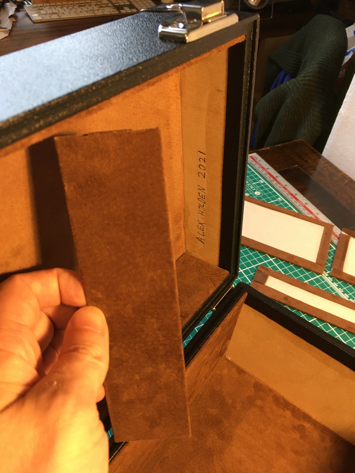
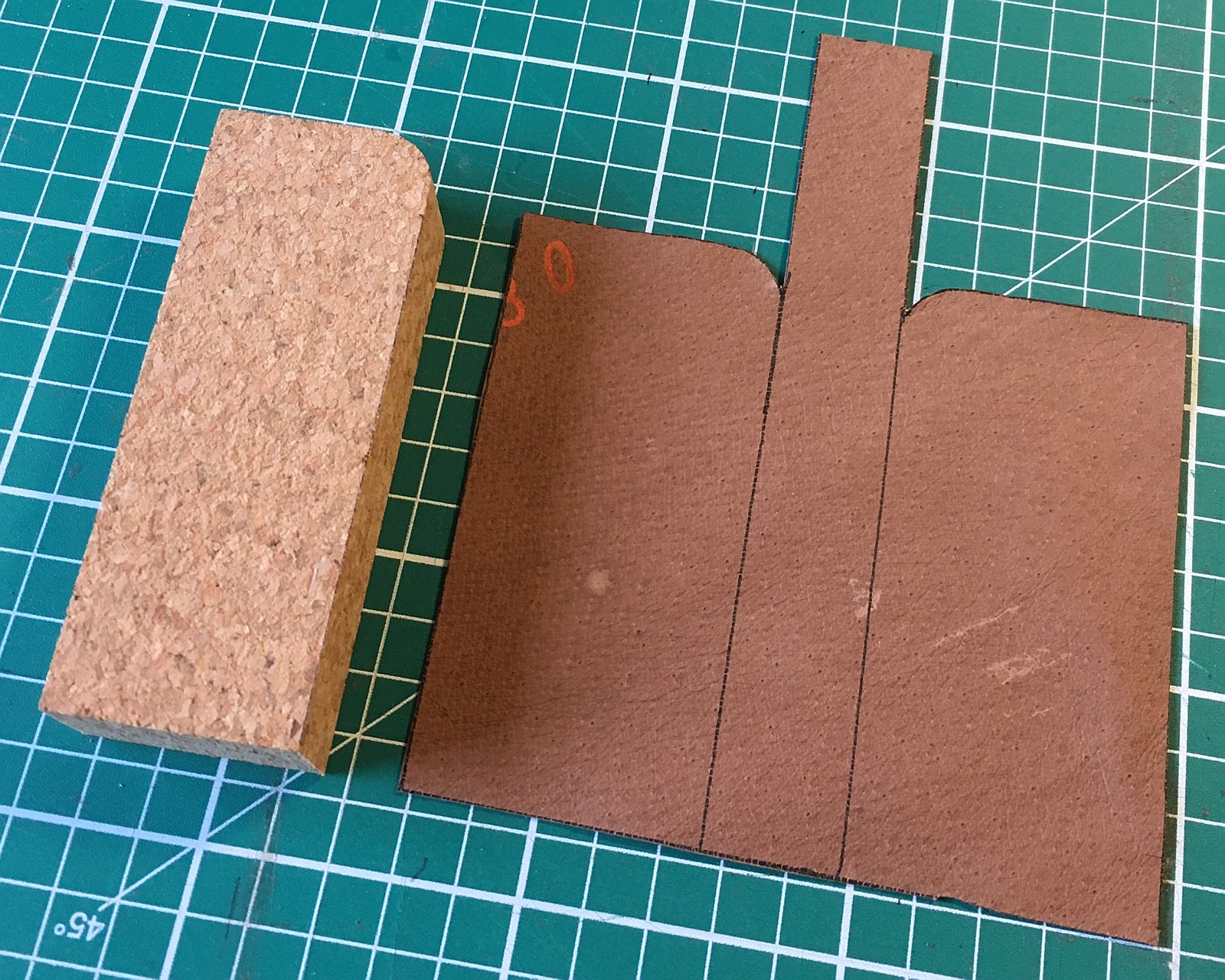
The corner blocks were cut from solid cork to reduce weight, then upholstered and glued directly into the already-lined corners of the box. This solution proved easier and neater than what I did on No. 9’s case.
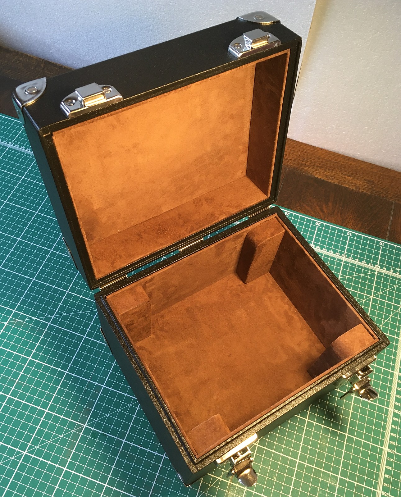
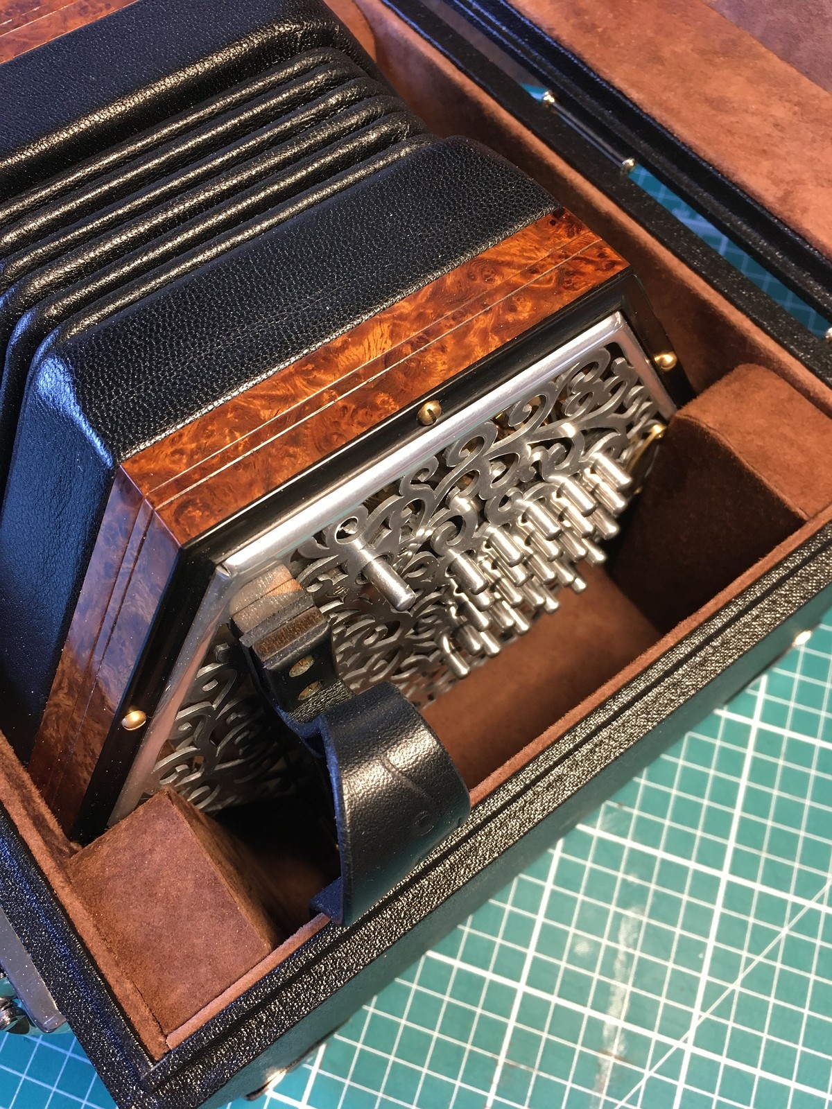
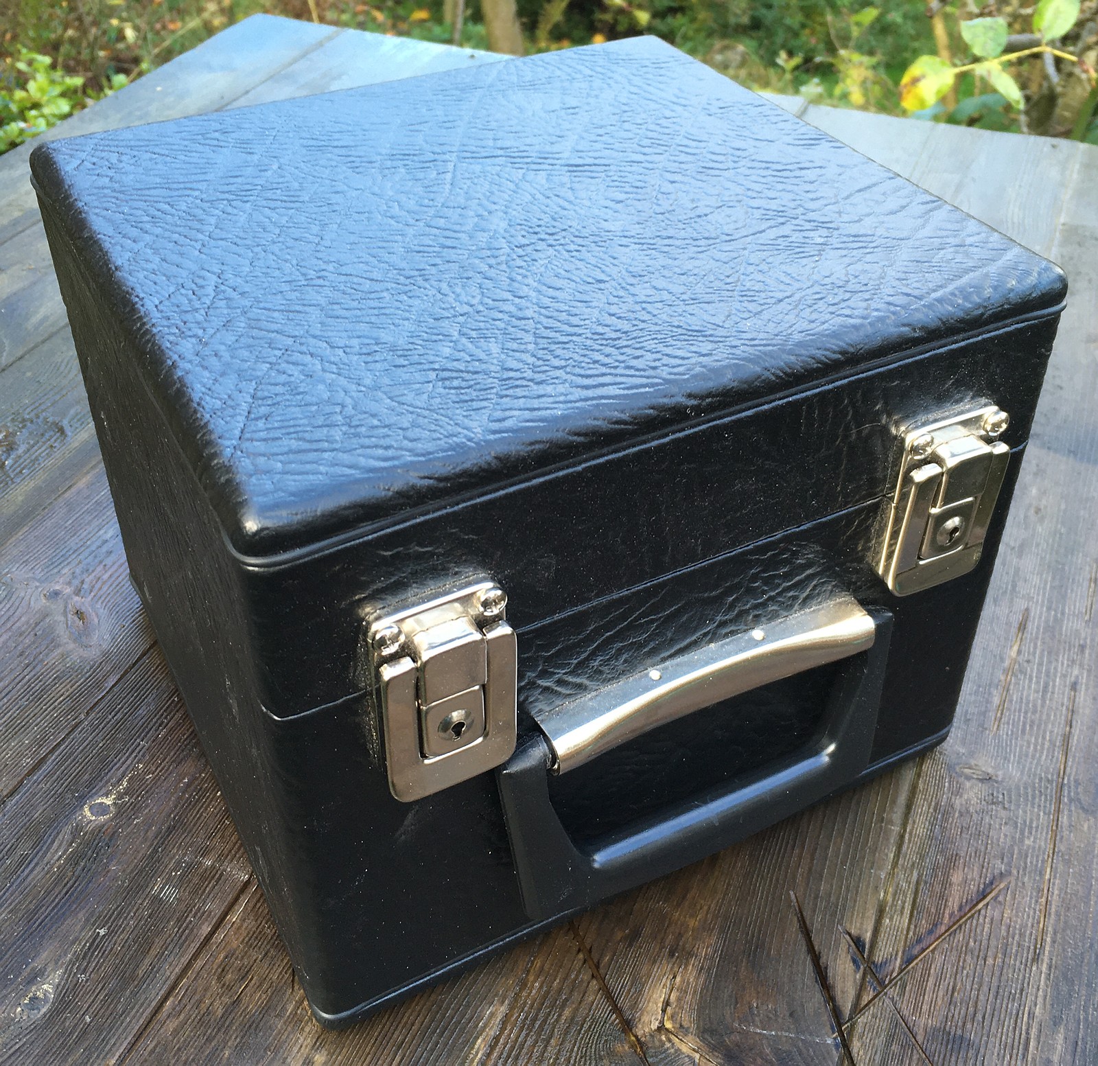
I’m quite proud of how professional, functional, and luxurious-looking this case turned out.
After receiving No. 10, John also asked me to rip out the original red fake fur lining of No. 4’s hard case (easier said than done – it was glued in extremely well!) and reline it to match No. 10’s case. I plan to put this style of lining into all future standard cases.
Incidentally, another change John asked me to make to No. 4 while I had it back for a service was to replace the left hand Eb3 (which he almost never used) with an F2. Because the reed pan wasn’t originally designed for such a low note in that position, I had to use an undersized reed and heavily weight the tip, but it actually performs fairly well and sounds really nice in an F major chord.