Toolmaking

No. 1: Brun Part 5: Bellows

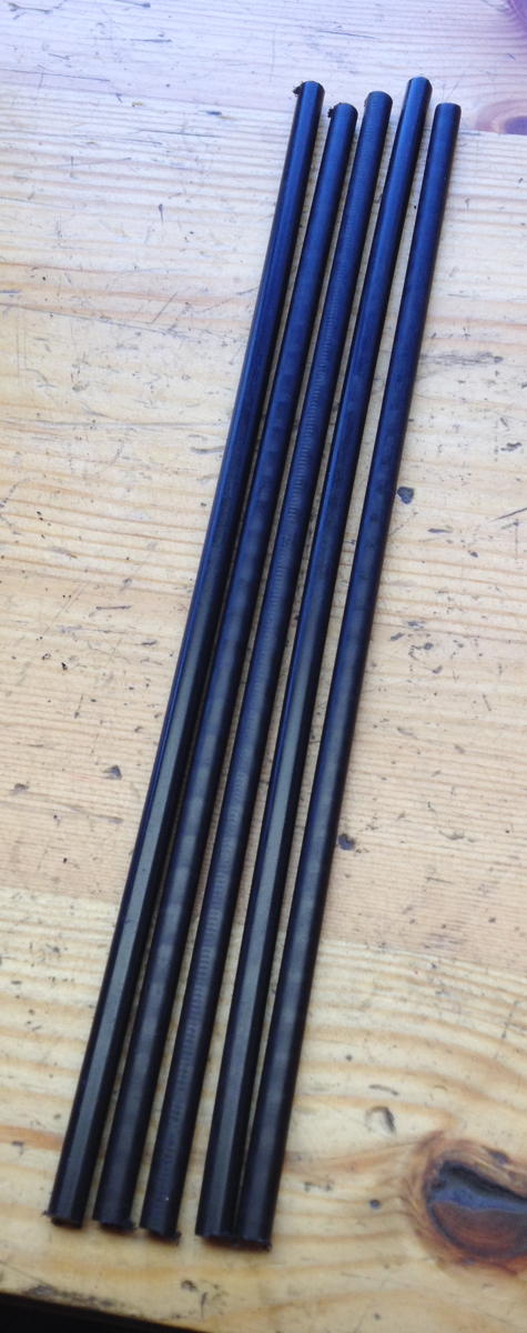
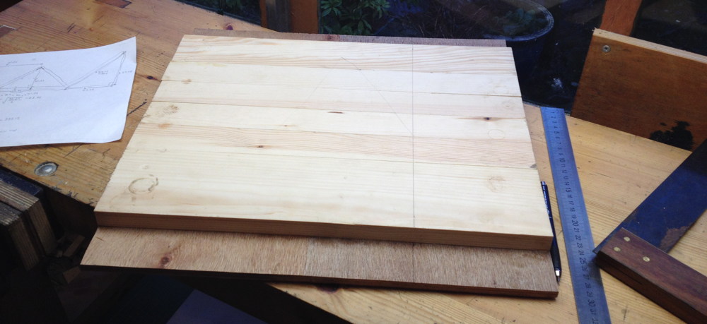
The fifth instalment in the story of building my first concertina is about the bellows. First I had to make a new, rectangular mould to assemble them on. The stock for the forms was constructed from strips of softwood glued across a plywood base, which I then ripped into four pieces.

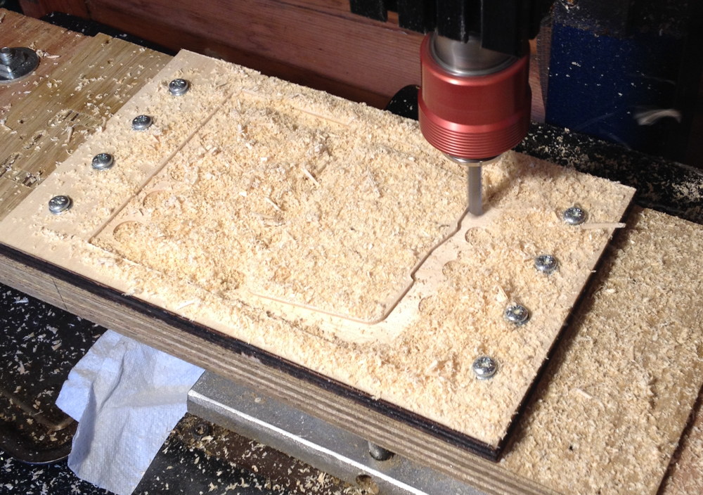
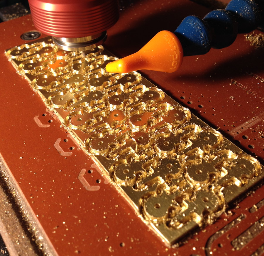
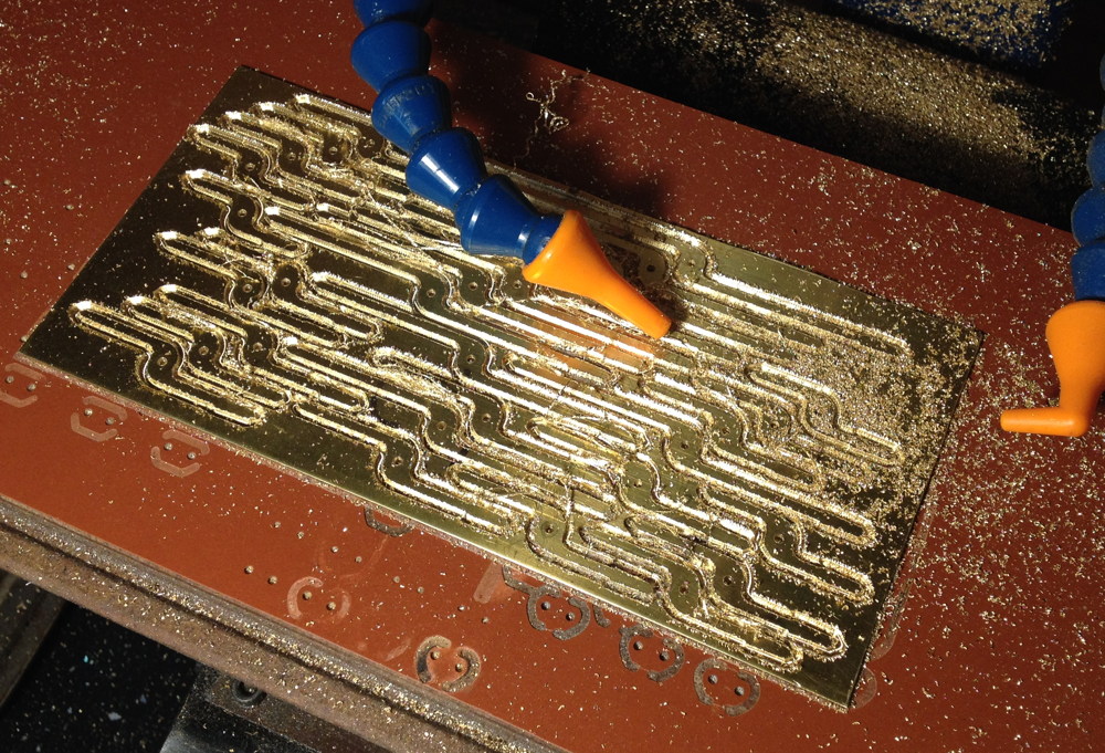
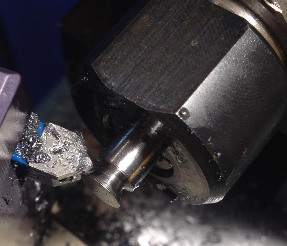
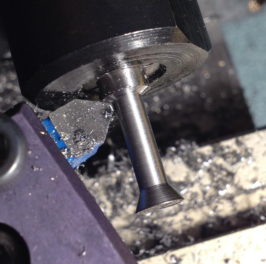
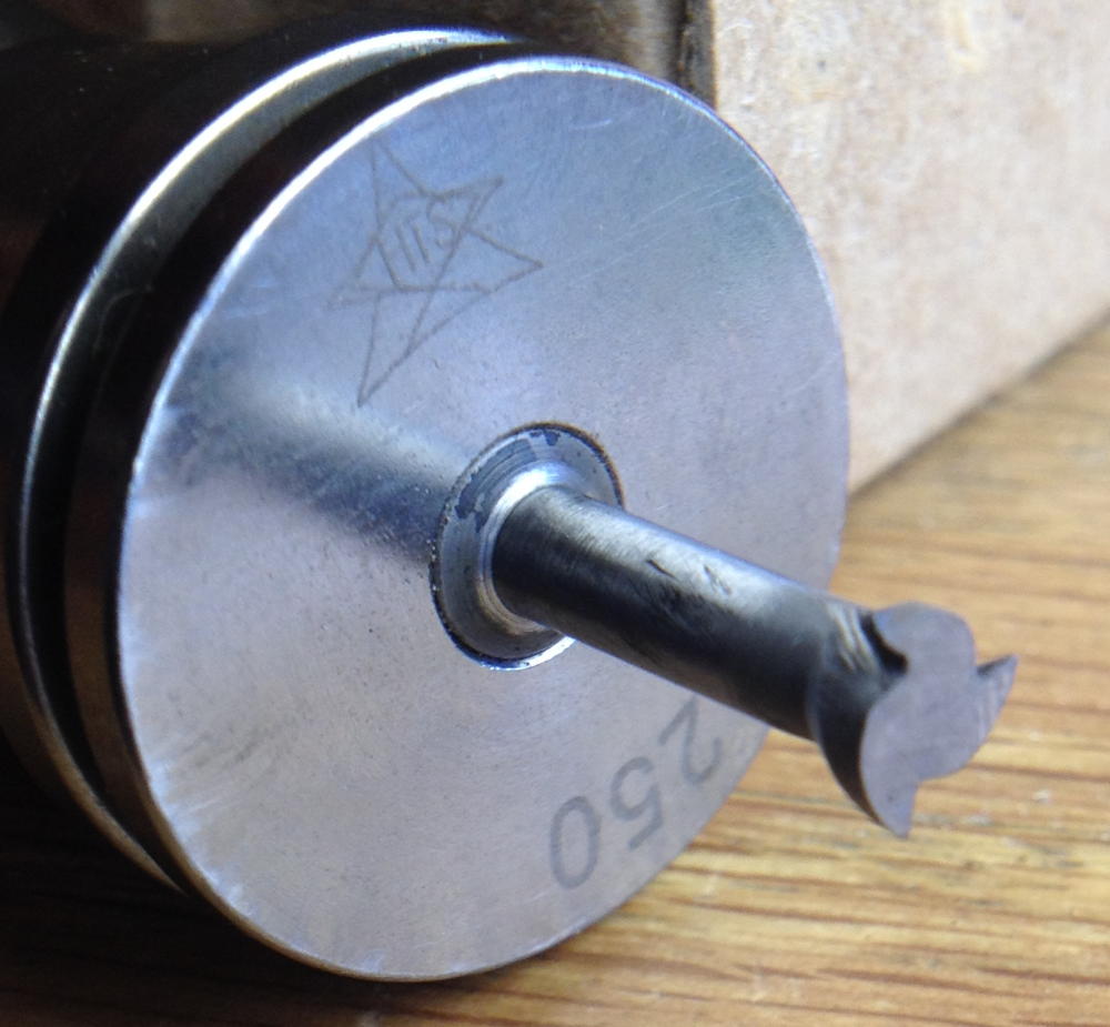
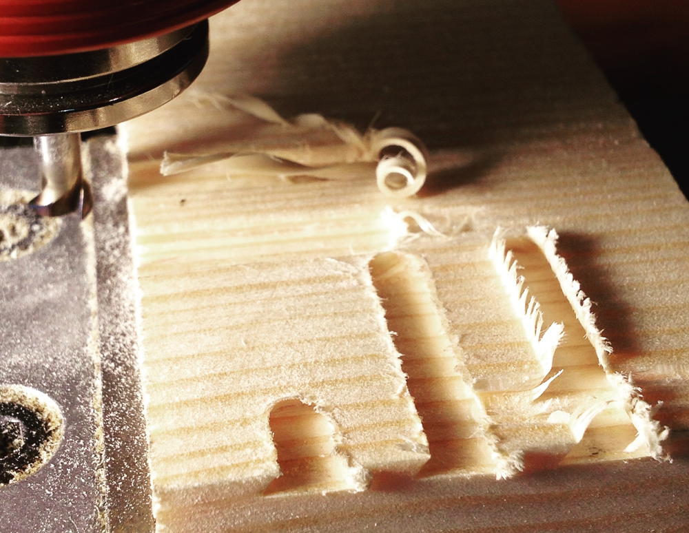
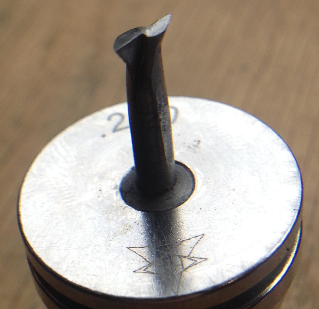
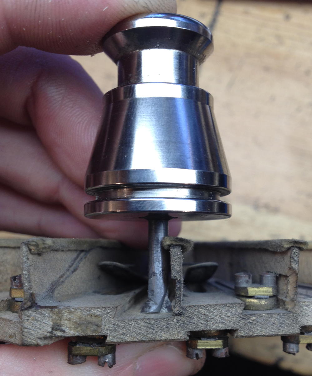
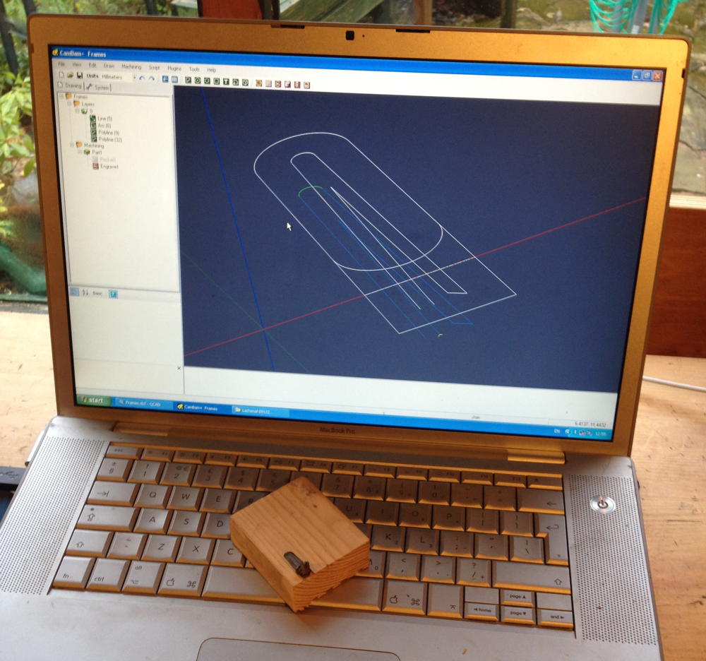
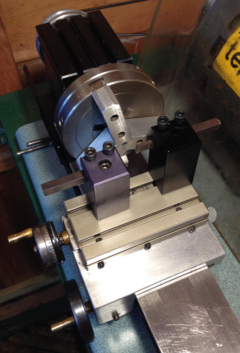
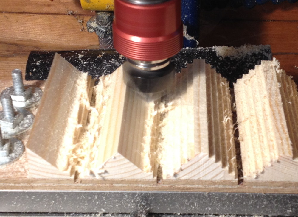
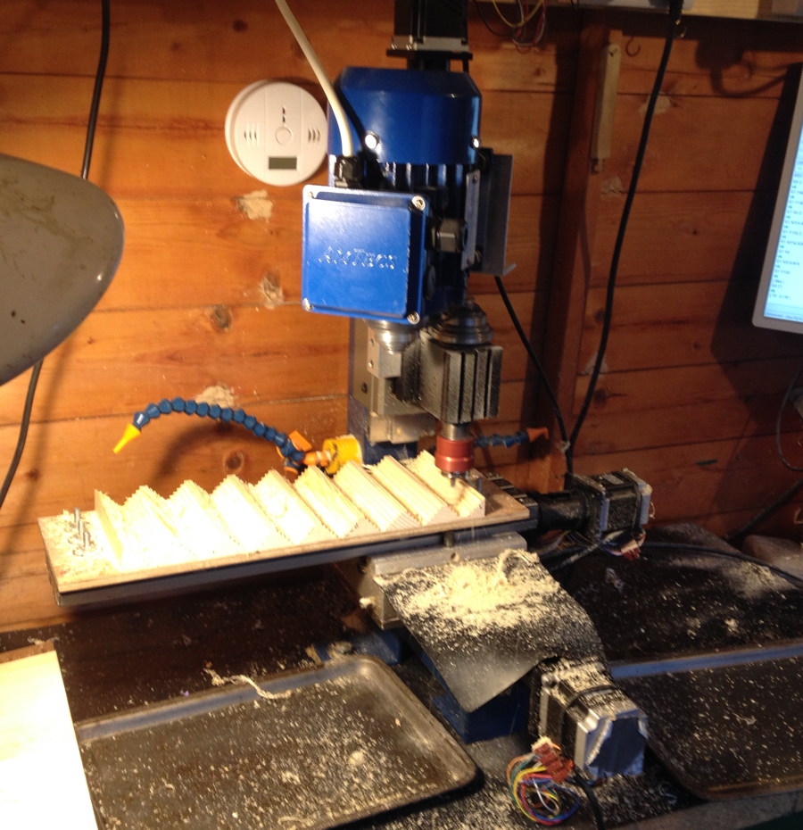
I again milled the forms to shape on the CNC mill. One thing I did differently this time was to rough them out in staircase form with an ordinary ¼” end mill first before cleaning them up with the large V bit.

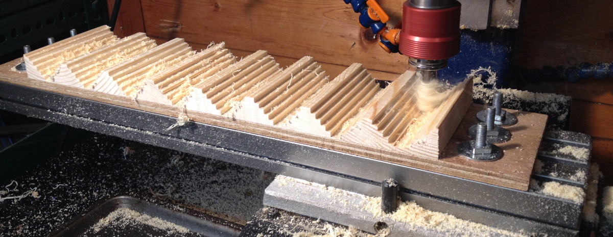
When I made the forms for the hexagonal mould, I cut straight into the material with the V bit using lots of shallow passes, which caused lots of noise and vibration, resulting in a poor surface finish. Removing most of the material with an end mill first gave much better results.

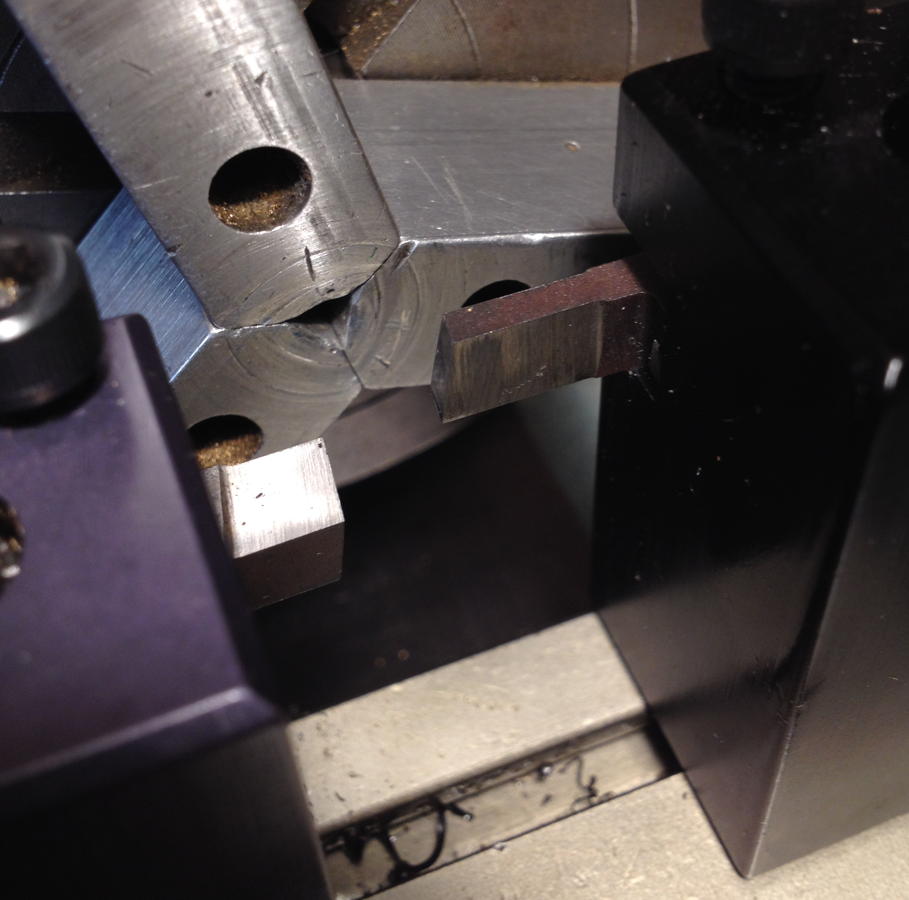
The wide forms stretched the machine to the absolute limit of its Y axis capacity.

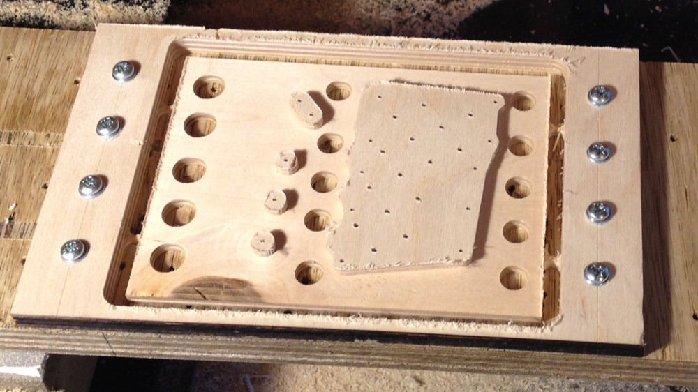
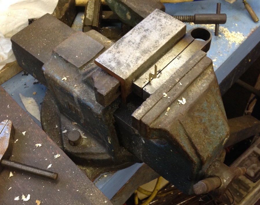
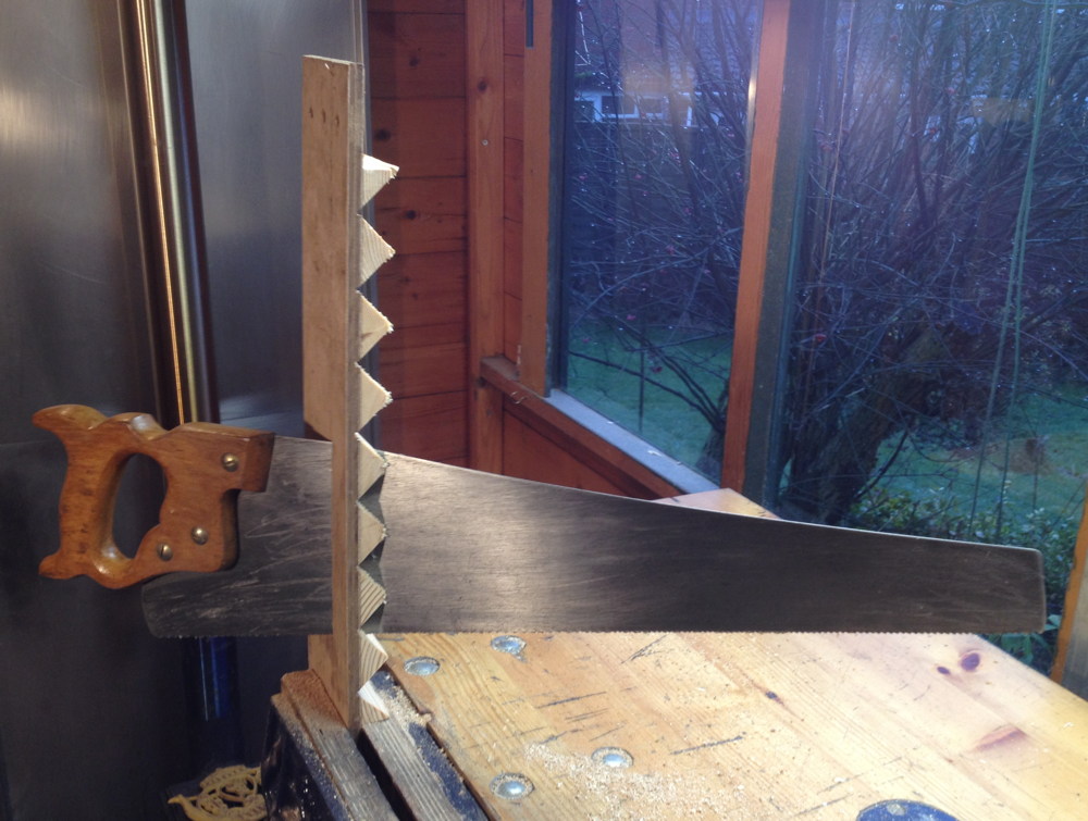
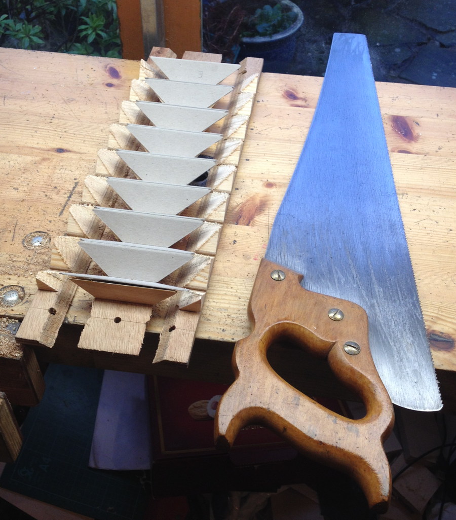
The bandsaw I had at the time wasn’t capable of ripping the angles off the undersides of the forms, and I don’t own a table saw, so I did them with a hand rip saw instead.

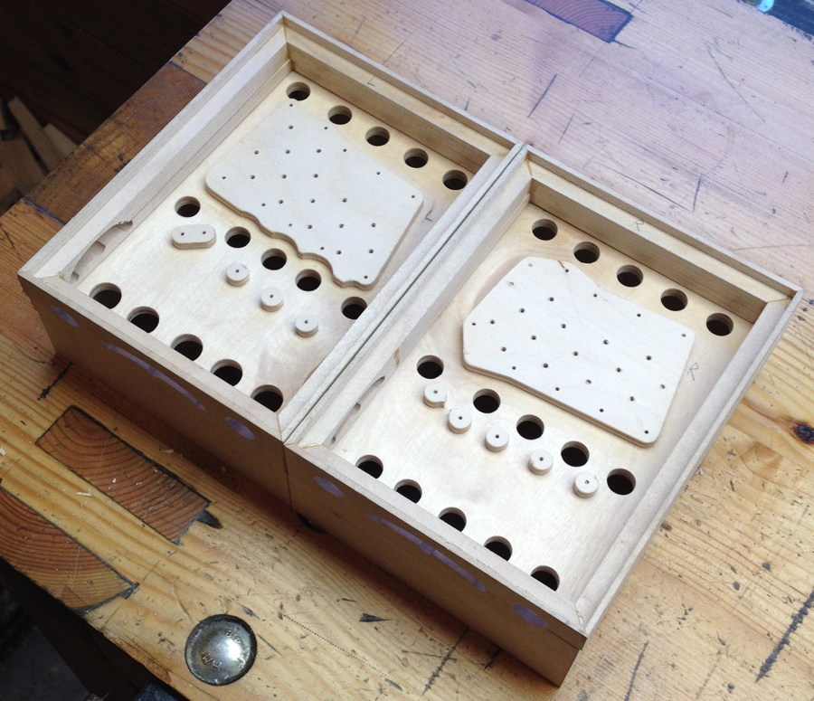
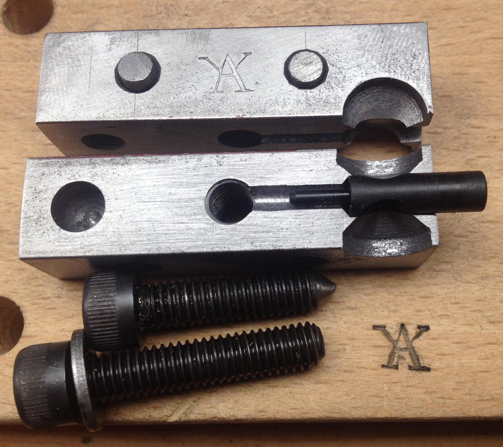
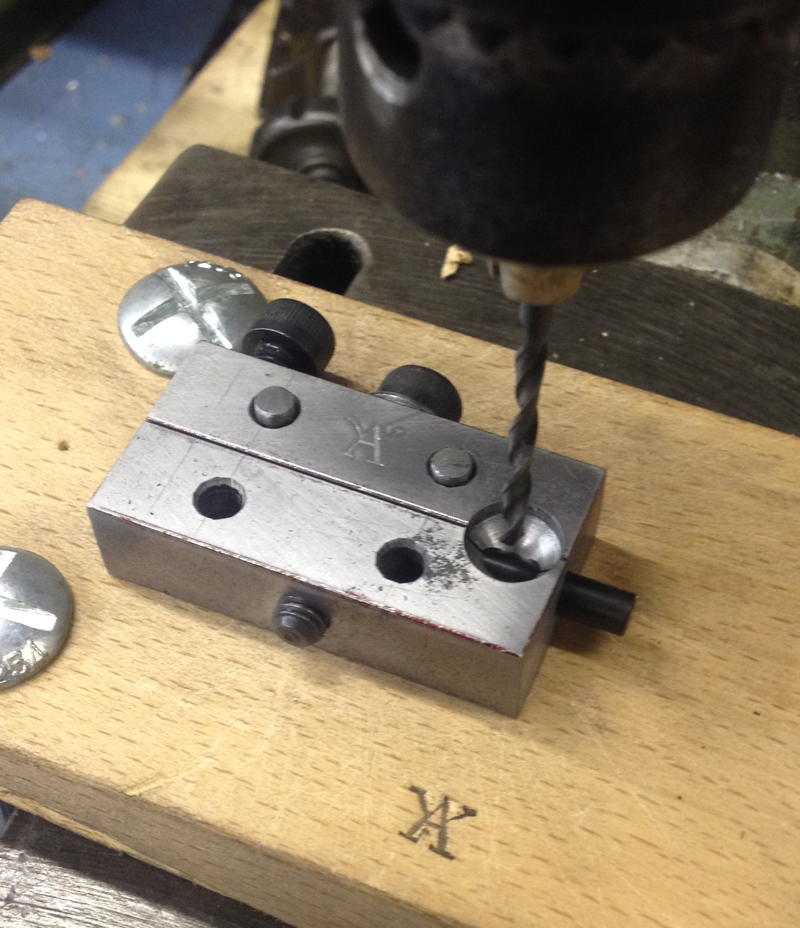
The rectangular core was relatively simple to make compared to the previous hexagonal one.

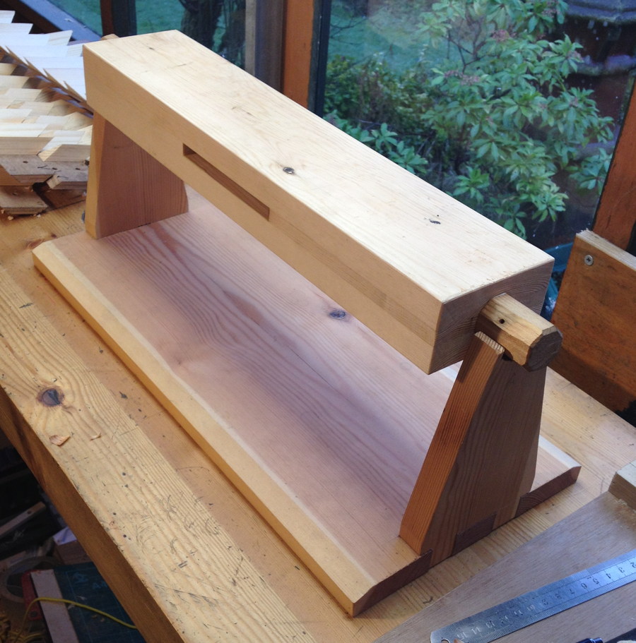
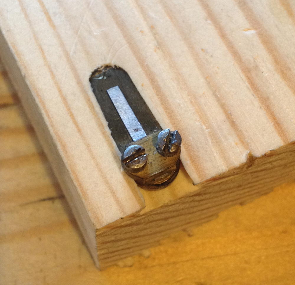
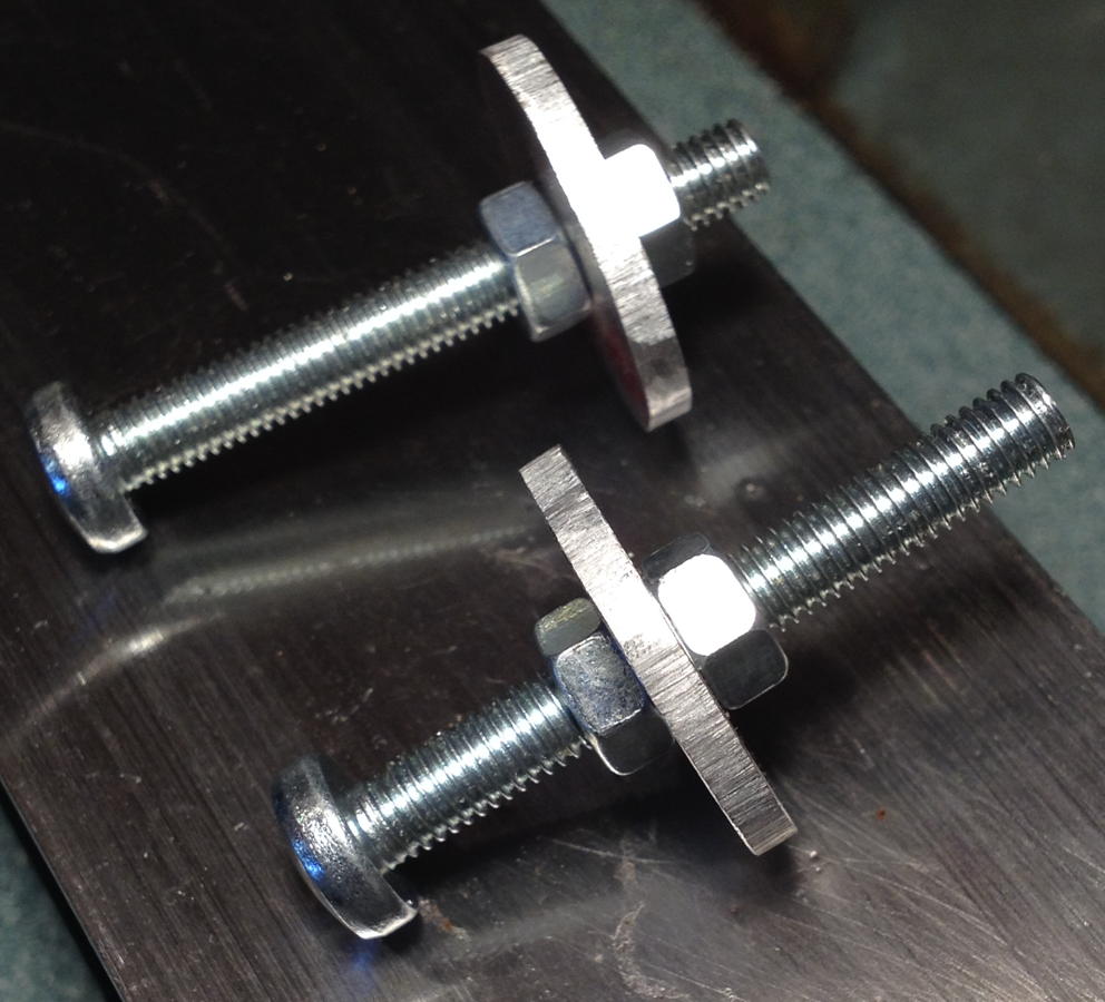
I split both of the long sides to make the mould easy to remove from the finished bellows.

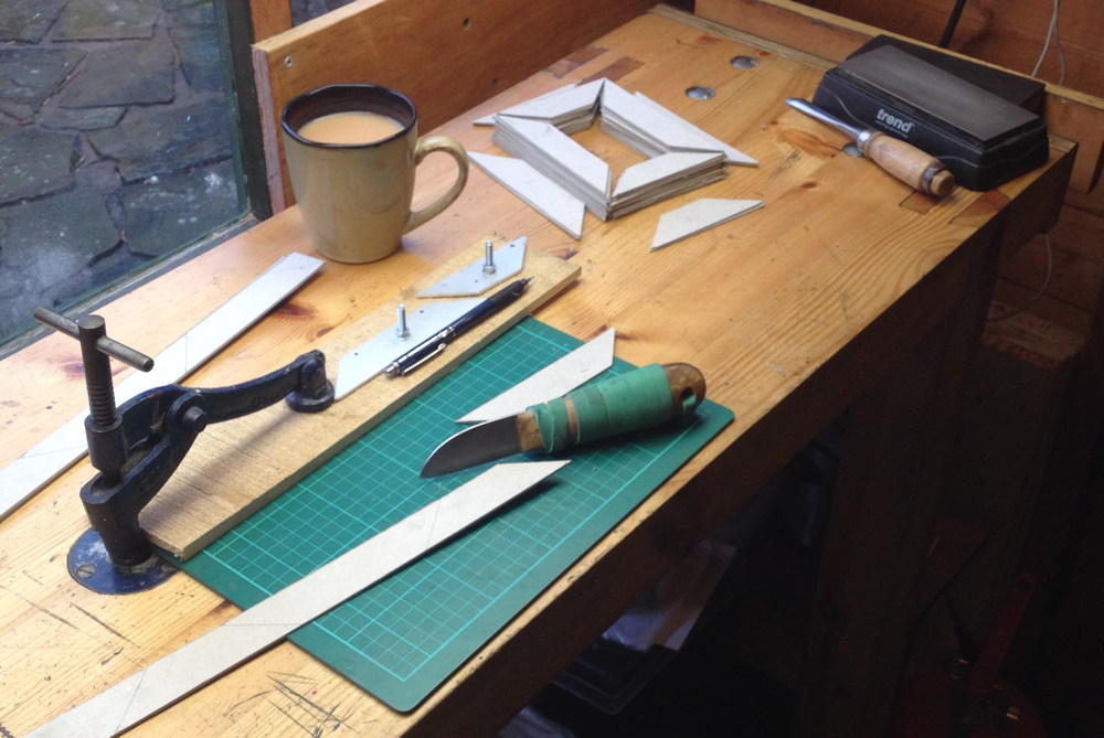
Cutting the cards by hand with a craft knife. I hate this part; it makes my knife hand ache for days afterwards. Also, because this set of bellows was meant to be relatively heavy-duty for a ‘travel’ instrument, I chose to use thicker 1.5mm card rather than the standard 1mm stuff I used on the tuning bellows (in hindsight this may not have been a good idea because it made the bellows a bit bulkier). I have since bought a special card cutting guillotine that in the future will make this operation much quicker and easier.

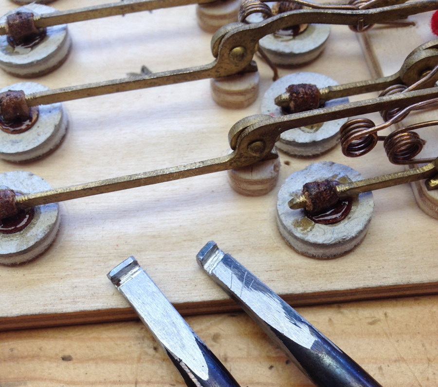
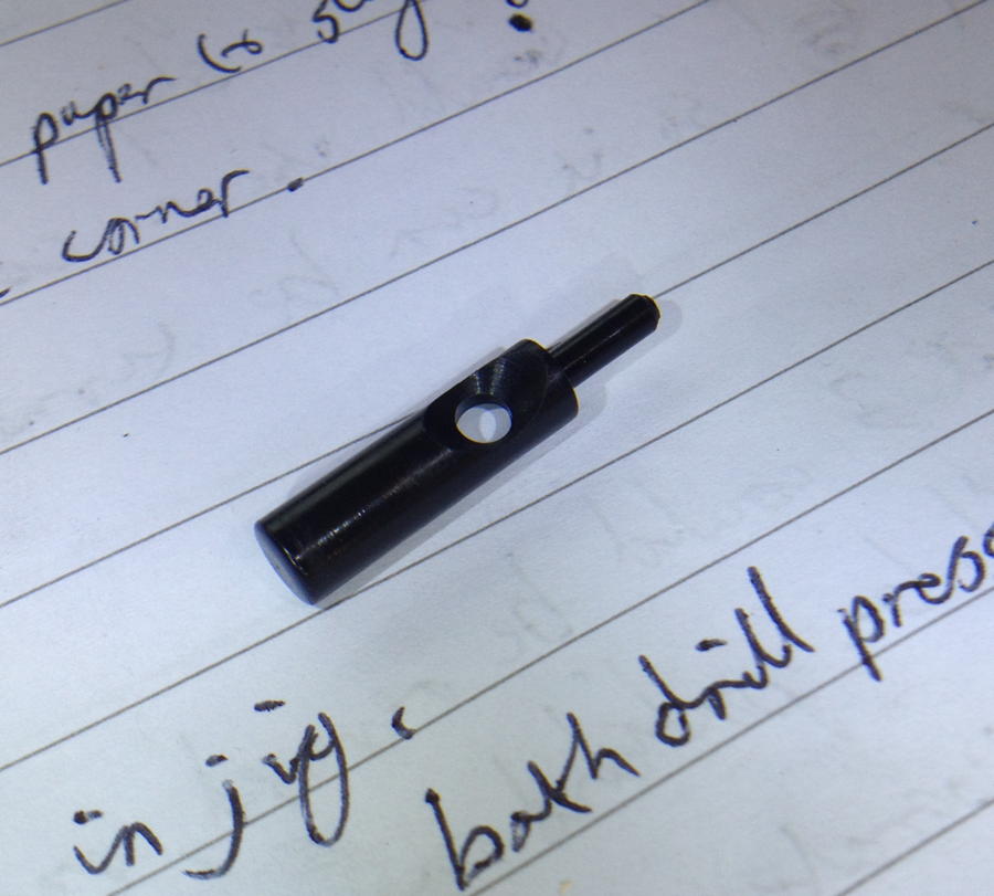
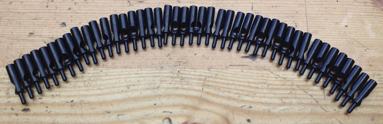
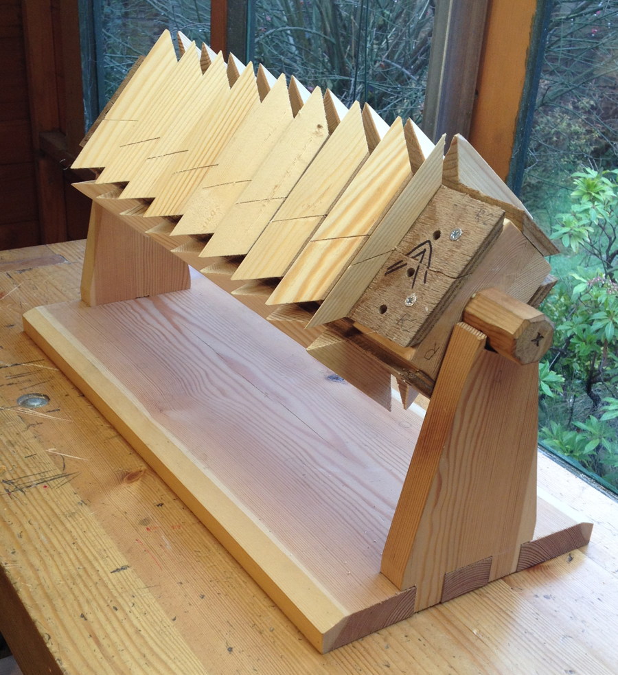
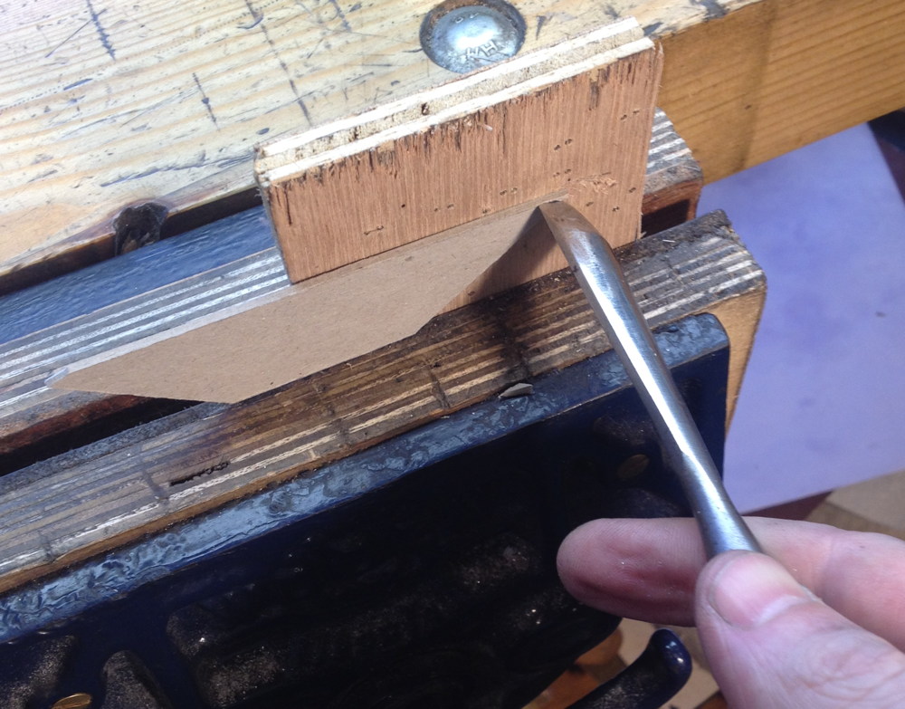
Rounding the corners of the cards with a gouge. I started off pressing down onto the bench, but I found it was easier to put a cutting board in the vice and lean against the gouge handle with my hip.

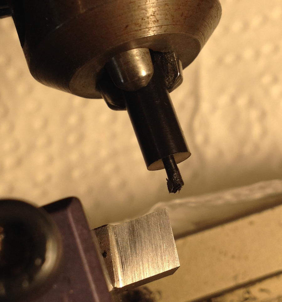
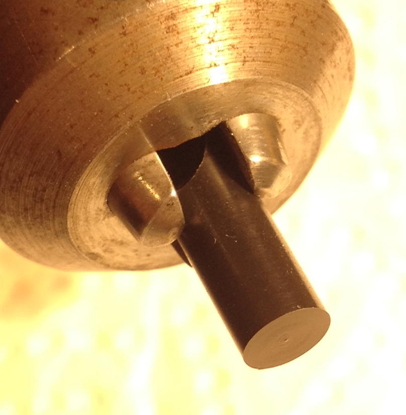
I rounded the tops of the cards on a linisher (bench mounted belt sander) with an 80 grit belt. In hindsight I should have done this outdoors because everything in the garage including my car wound up covered in a thick coating of fine grey dust!

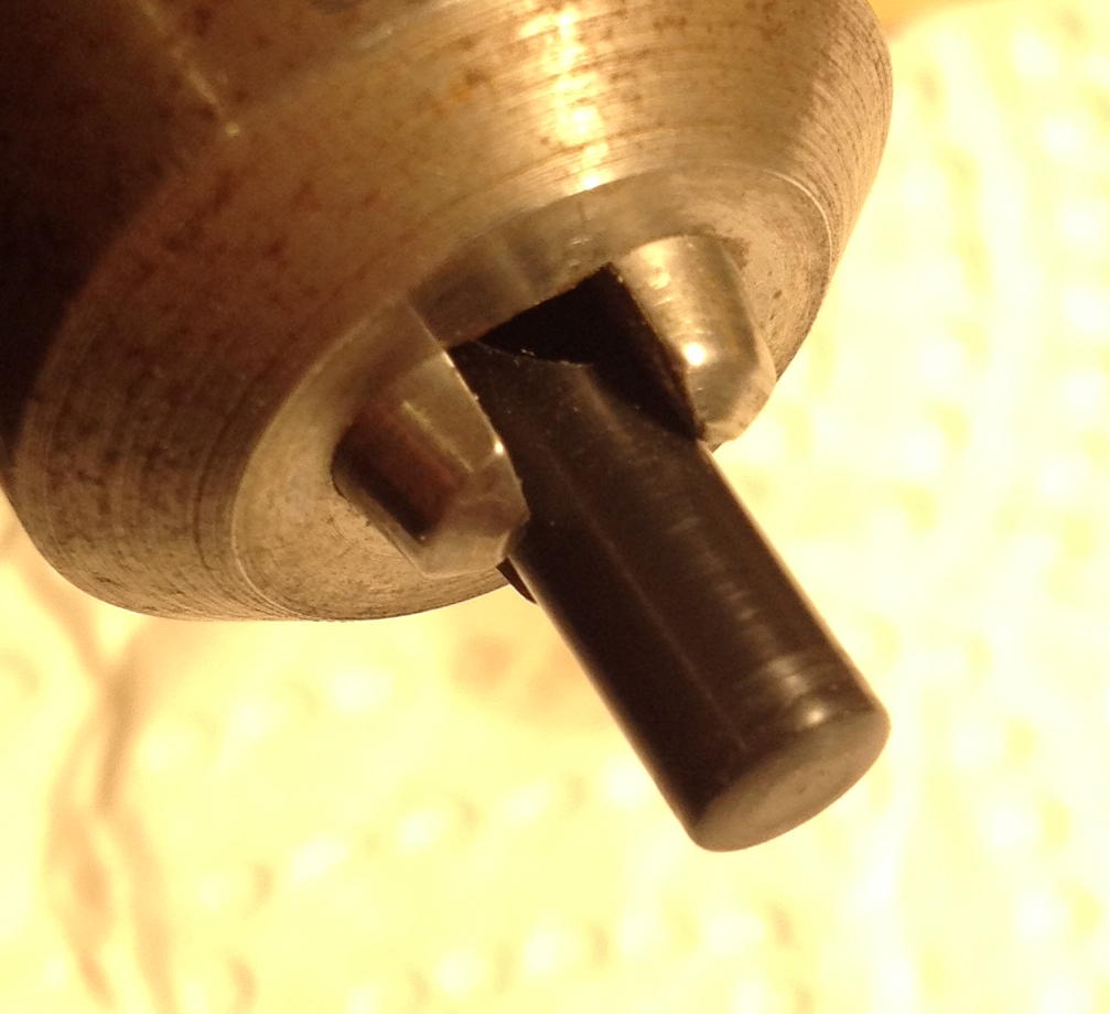
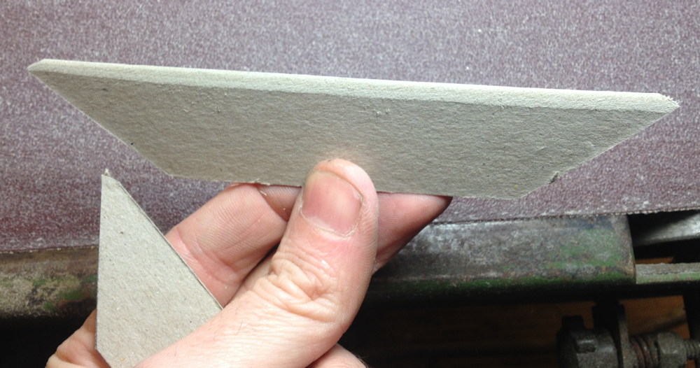
The rounded top of a card. This gives a nice shape to the peaks of the bellows folds, though in hindsight it would have looked better still if I had rounded the pointy corners a bit more.

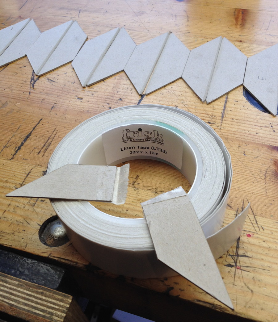
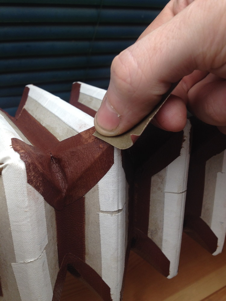
I decided to try hinging the cards together with a self adhesive linen hinge tape made for bookbinding and other card related crafts. The roll was quite wide so I cut it in half. This picture shows the result of a strength test: the surface of the card ripped off before the glue or the linen failed (and it took quite an excessive amount of force to do so).

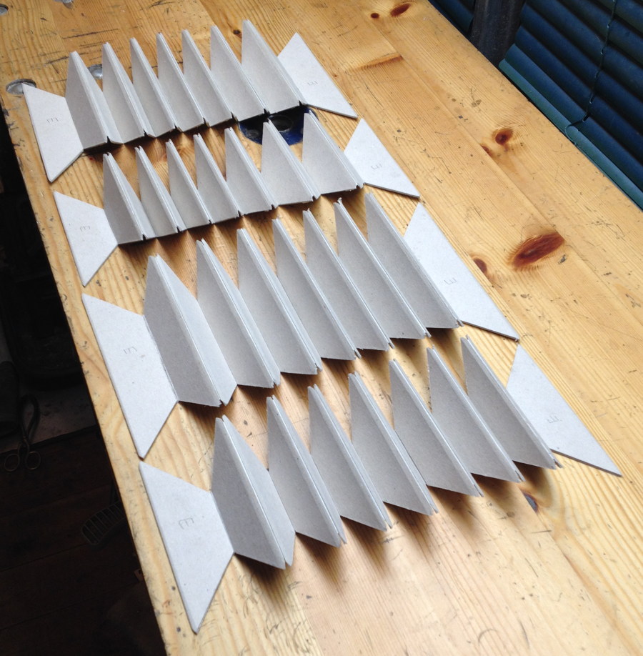
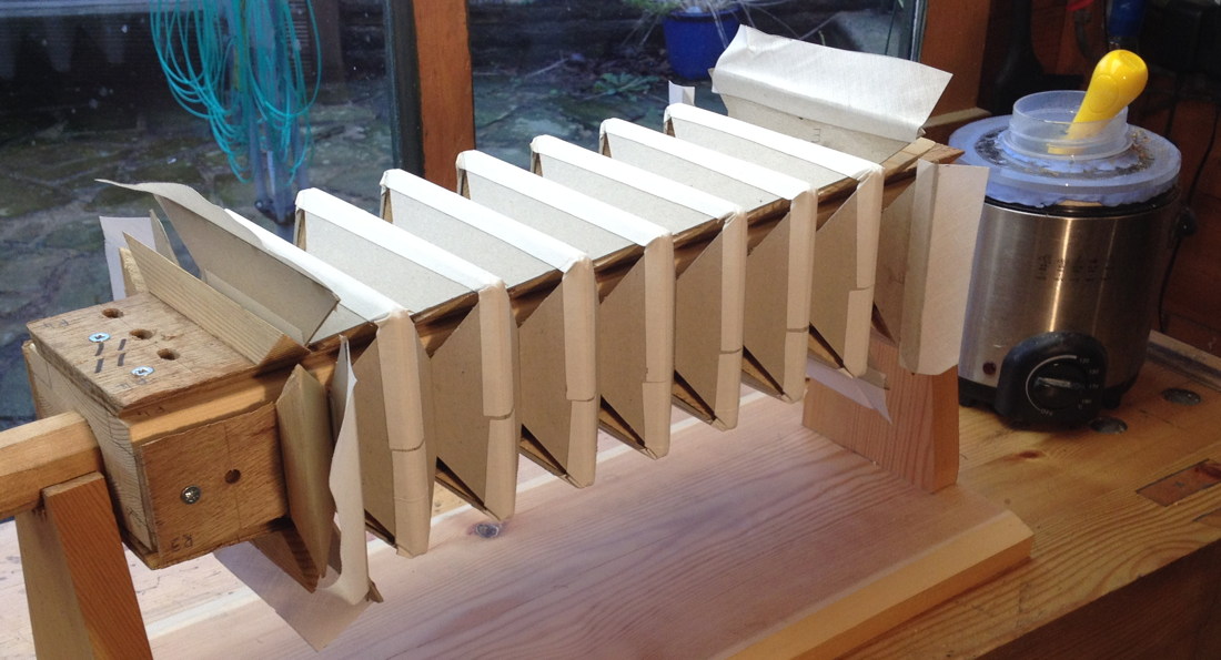
I started by hinging the cards together on the inside. The peak hinges can be taped with the cards laying flat, but it’s better to do the valley hinges with each pair of cards in the closed position (or flat but with spacers holding a slight gap between them), otherwise they will later resist closing.

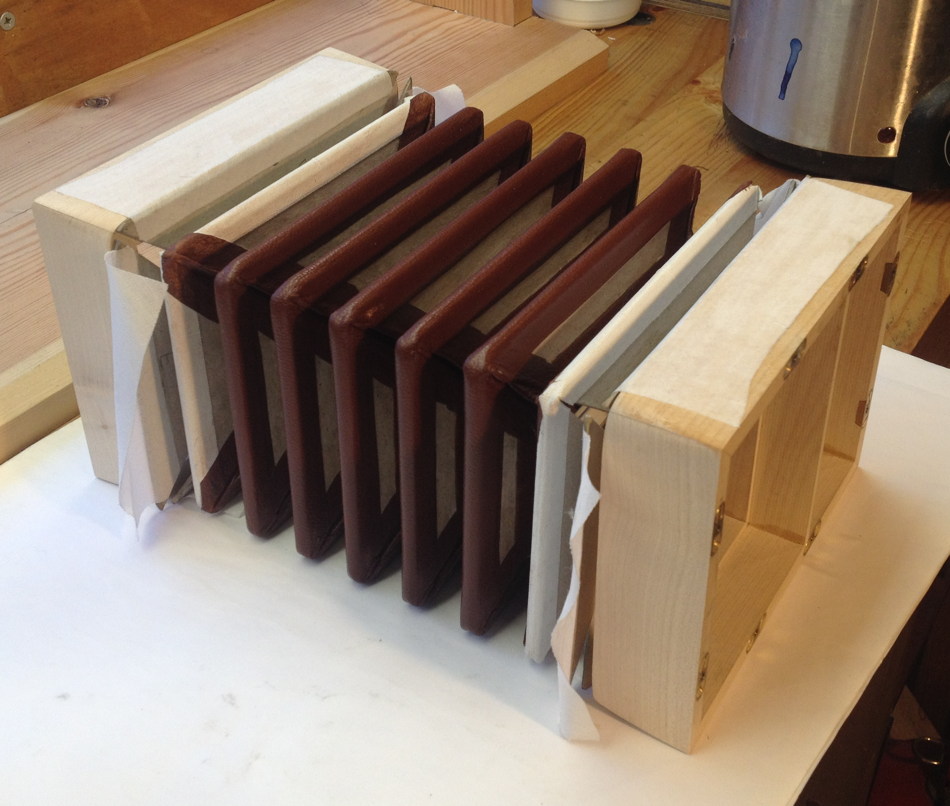
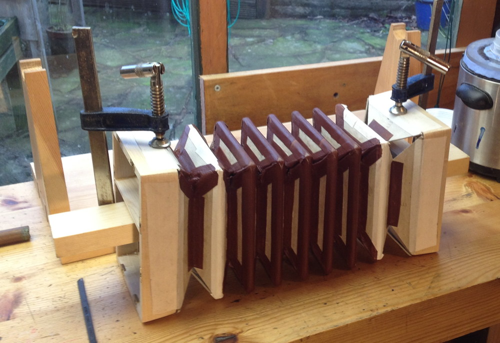
I folded them up and clamped them tightly like this for a couple of days to help the tape glue to really bond well to the cards. Note that the end cards are slightly taller because the end boxes are about ¼” bigger than the bellows. This is partly cosmetic and partly to avoid the bellow peaks touching the table when you put the concertina down.

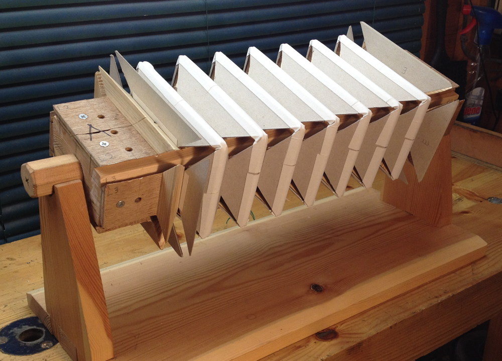
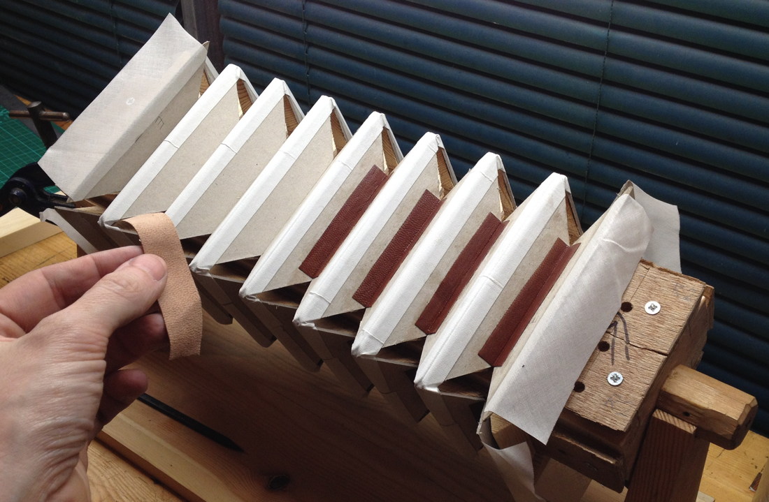
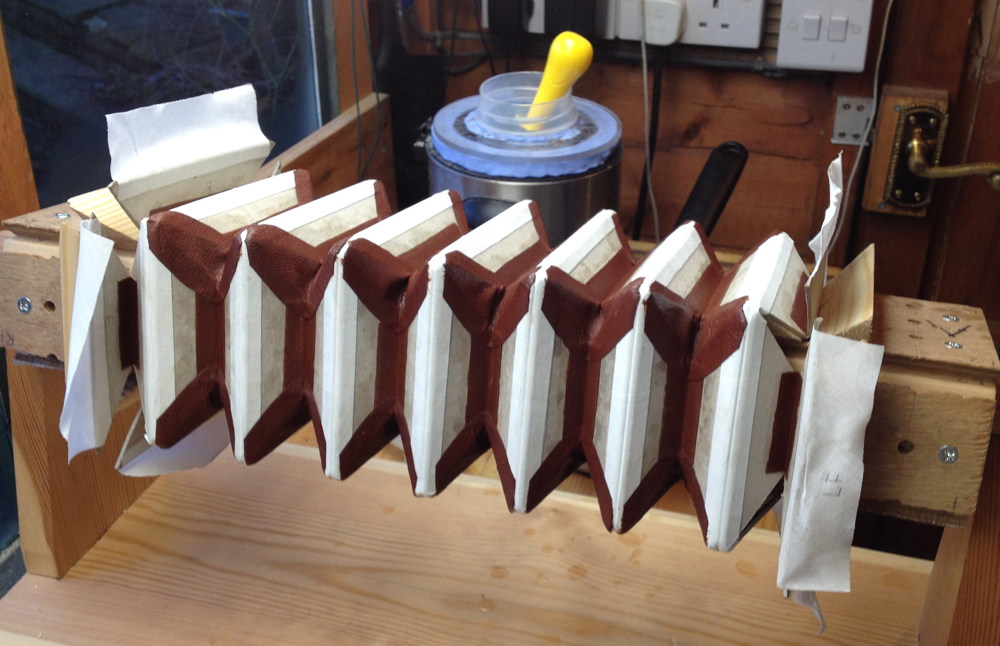
Next I tied the sets of cards to the mould with plastic coated gardening wire. Elastic bands would probably have been easier but I didn’t have any long enough. Note that the bellows frames aren’t attached to the mould. This wasn’t possible with this instrument because the frames have a divider across them due to the split reed pan design.

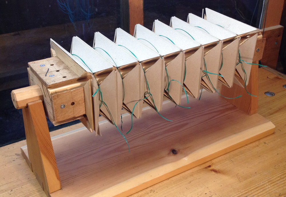
I ran the self adhesive linen tape all the way around each peak. This gives a stronger bellows than if you just put small pieces on each corner.

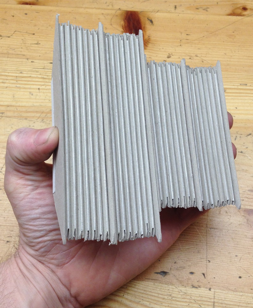
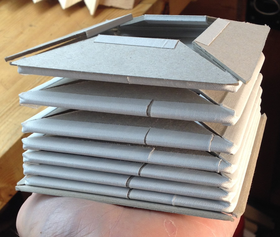
Afterwards I took the full set of cards off the mould and again pressed it tightly for a day or two to help the top hinges stick as well as possible. You can see in this picture what I meant about how it would have looked neater if I had rounded the corners of the cards a bit more.

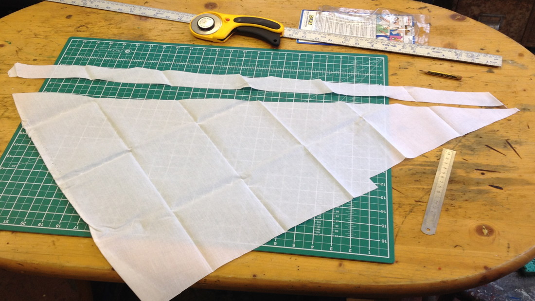
I needed wider hinge strips on the end cards to attach the bellows to the frames, so I cut those from the ‘Fraynot’ hinge linen from Shepherds bookbinders’ suppliers that I used for all the hinges on my tuning bellows. I cut it on the bias to make it less likely to fray or rip.

Then I glued them on. From this point on, I used hot rabbit-skin glue for everything except the decorative papers.

A brief digression about my experience with the self adhesive hinge linen. In future I’m going to go back to using the Fraynot linen cloth for everything. Although the self adhesive tape worked fine and I don’t think it’s likely to come apart, I found that I much prefer working with the Fraynot and a liquid paste/glue, because if it goes on wonky you can peel it straight off and reposition it, whereas the self adhesive tape sticks instantly and you have to tear the surface of the card to get it off again, then throw away that strip of tape. The tape is surprisingly expensive too, though that’s not my primary consideration. It also had quite a lot of wrinkles in it where the cloth had stuck to itself during manufacturing and the glue is so strong it’s not possible to pull the wrinkle out; sometimes I had to waste a section of it to avoid putting a wrinkled piece on the bellows where it would be visible through the leather. Most importantly, I believe the hinges I get with strips of cloth are noticeably thinner and more supple than with the tape. The difference is fairly subtle when looking at a single hinge, but an entire bellows set with hinges on both sides of the peaks feels relatively stiff and bulky when assembled with the self adhesive tape. Although it’s possible the tape is made from a heavier cloth, I suspect the main difference is in the properties of the glue. I have found that traditional wheat paste doesn’t noticeably stiffen the hinge at all, whereas rabbit glue does stiffen it a little initially but after working it for a while it ‘breaks in’ and becomes supple again. Whatever is on the self-adhesive tape has a rubbery feel to it, and seems to add a bit to the thickness of the hinge too.

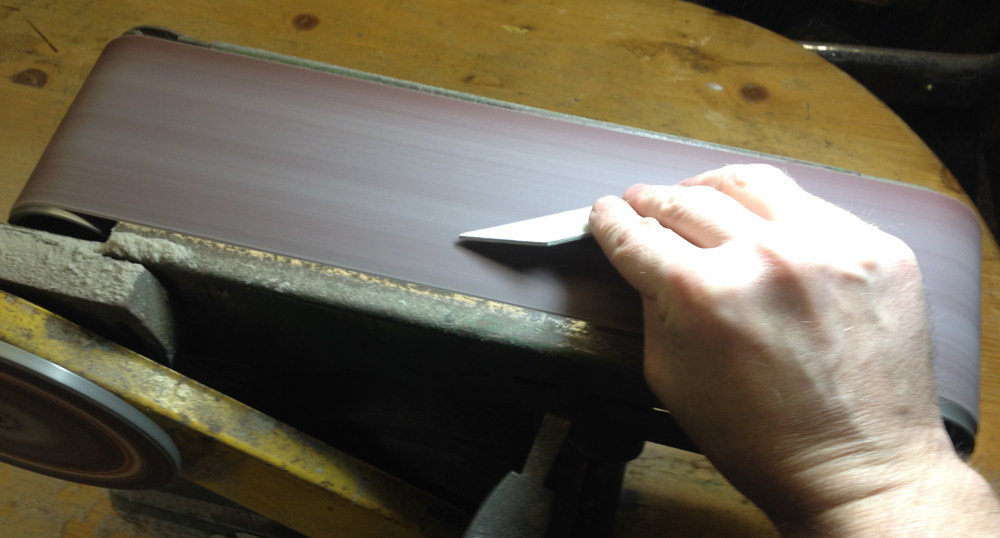
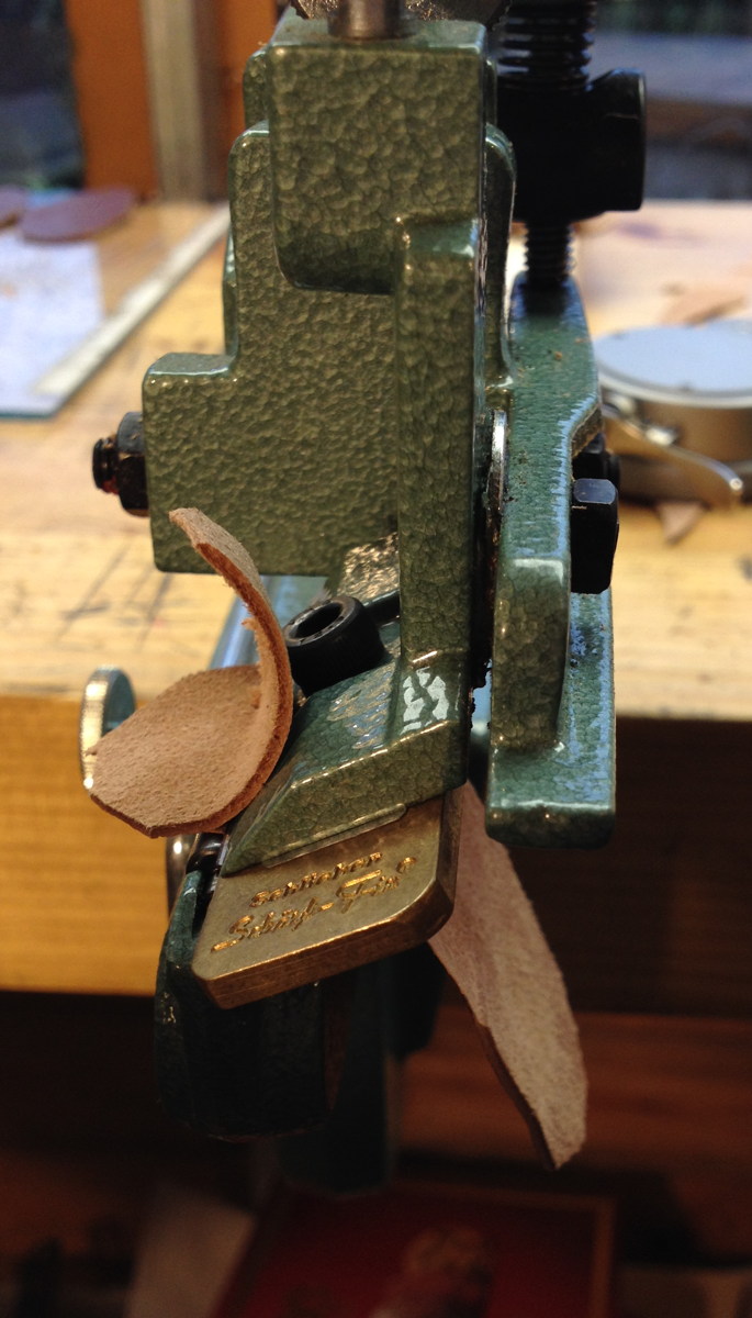
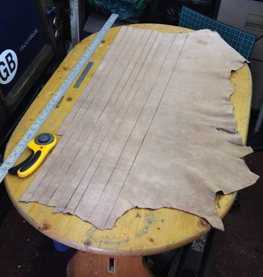
I covered the bellows with a nice brown goatskin leather from Hewit, cutting it into strips with an Olfa rotary cutter, which really cuts very nicely, much easier to use than a craft knife.
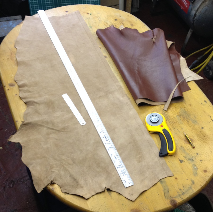
Using my Scharffix 2000 to pare the leather down.

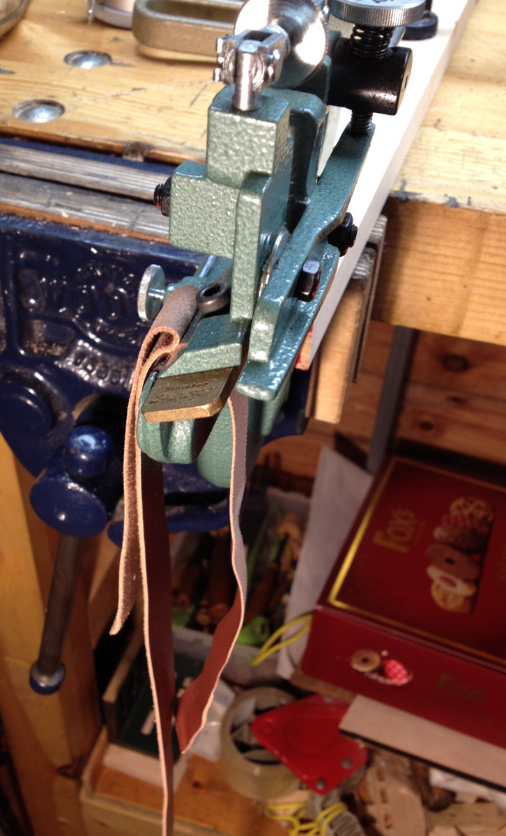
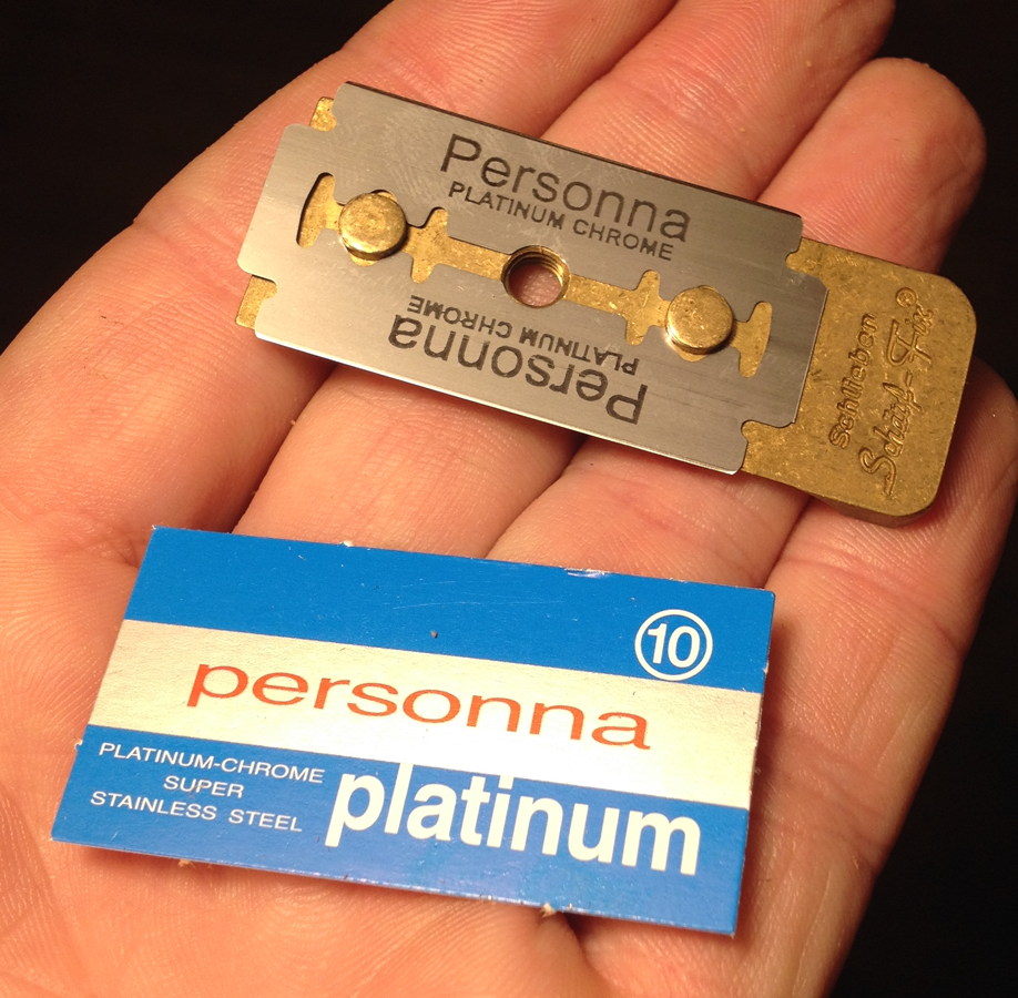
Thanks to a thread on the concertina.net forum, I learned that Israeli-made Personna safety razor blades fit the Scharffix and cut really well, better even than the thicker OEM blades that came with the machine. It’s crucial with this machine to use ultra-sharp blades, otherwise it behaves terribly, stretching and ripping holes in the thin leather.

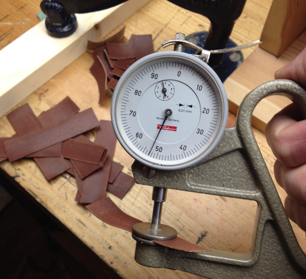
Checking the thickness of the valley strips.

And gluing them on:


Cutting out the gussets with a template and craft knife. This is rather a tedious job; a die tool would make it much quicker.

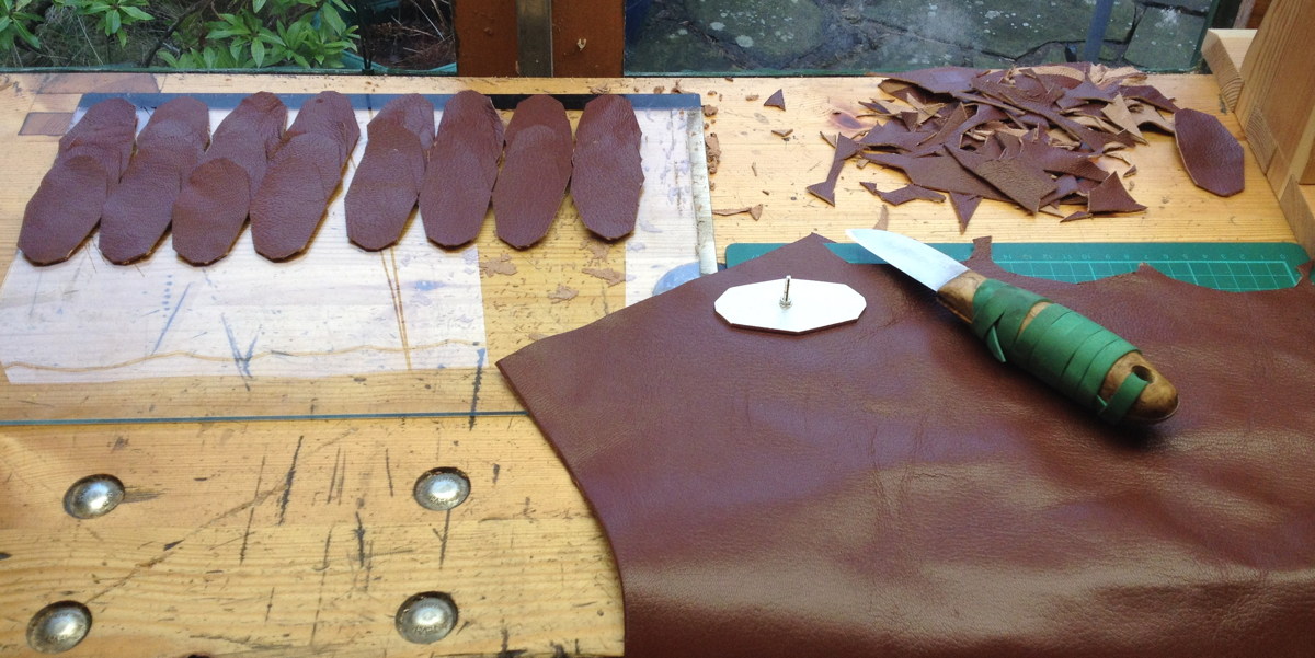
I use the Sharffix to do as much of the skiving as possible, but the gussets always need a bit of manual cleaning up afterwards with a skiving knife.

Gussets glued on. It proved rather a pain to get the bottom corners to fully stick to the valleys without leaving a little gap. I wound up waiting for them to initially dry, then adding a bit more glue to each gap with a tooth pick and pressing it down with a bone folder until it stayed in position. This is less of a problem with bellows that have more than four sides because you don’t have to stretch the gussets around such a tight angle.

I roughed up the tops of each gusset slightly with sandpaper before gluing the top runs over them.

Cutting more long strips of leather for the top and end runs. It’s a pain when the Scharffix goes wrong in the middle of one of these strips because you need the whole run to be good to avoid having more than one joint.
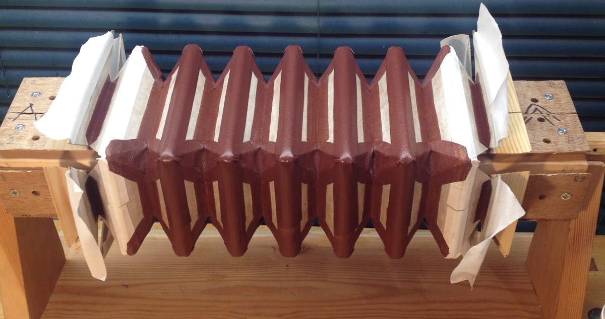
Top runs glued on.

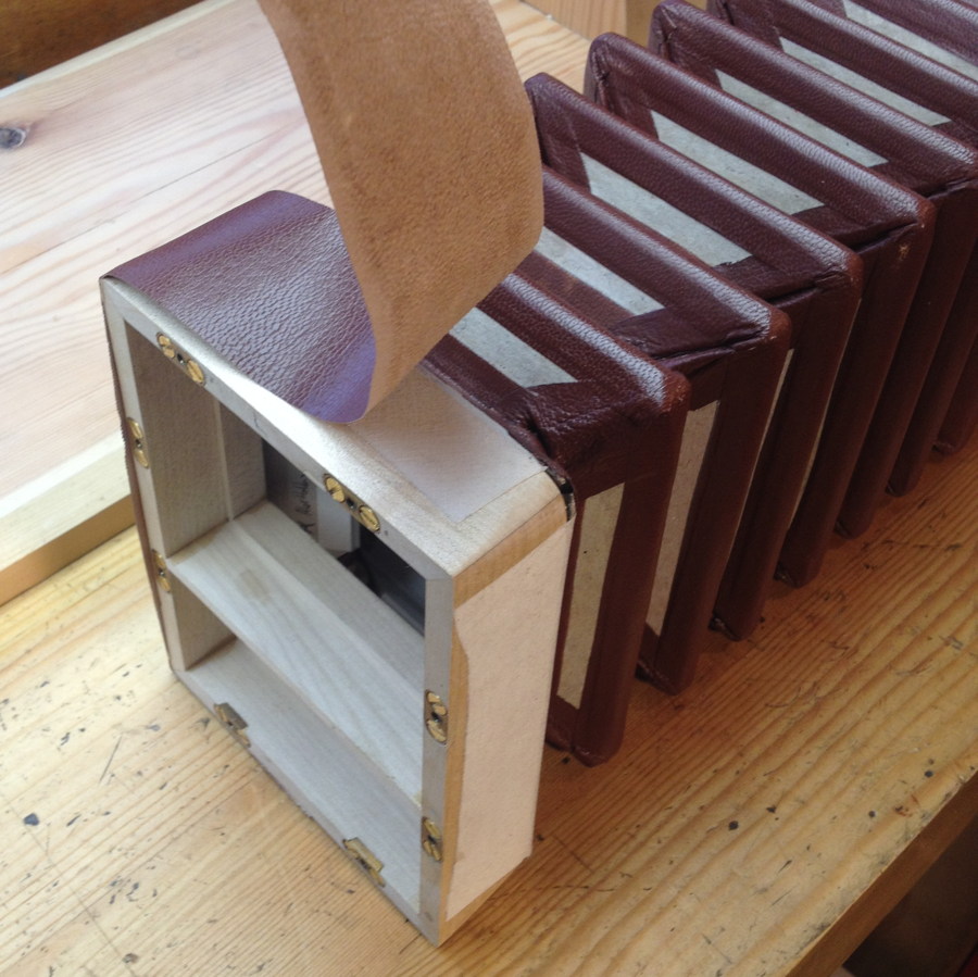
Next I needed to take the bellows off the mould and attach them to the frames, starting with the hinge linen.

Now the end gussets. This was way more difficult to do neatly without the aid of a mould. It helped to use a stick clamped to the frames to hold them a fixed distance apart.

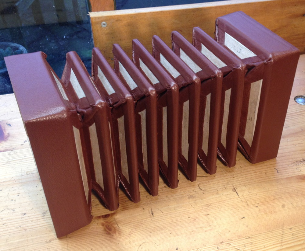
Finally the end runs. As I mentioned in part three, here’s where I realised I’d made a mistake in not making the bellows frames a tiny bit smaller than the action boxes, in order to hide the edge of the end run. I skived the edge down as close to nothing as I could and tried to get that skived edge flush with the edge of the frame, but it was impossible to get it absolutely perfect, so when I subsequently trimmed the extra off, the edge wasn’t infinitely thin any more so it is possible in places to see a tiny bit of unfinished leather. I recognise I am quite possibly being over-critical of my own work here!

Looking pretty good!

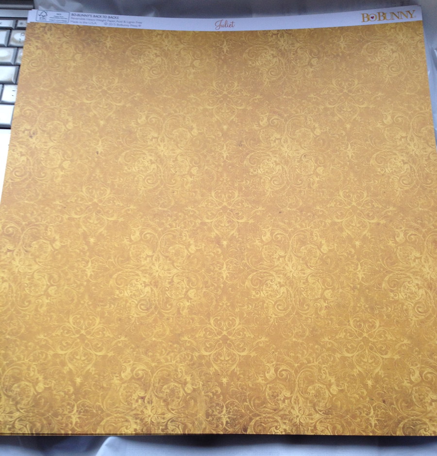
For the decorative papers, I took a sample of the leather down to my local craft shop and looked for a patterned decoupage paper that went well with it. This is what I found. I avoided cutting papers from the area near the bottom that looks dirty (the design is actually printed that way).

I spent a pleasant evening cutting out papers and pasting them on while watching TV programmes in the background.

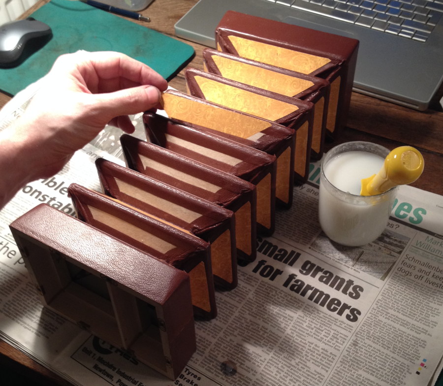
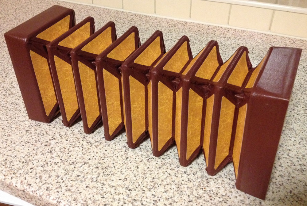
The finished bellows. I think the papers really go quite well with the leather. Although they were still quite stiff and springy at this stage with a preference for remaining open, I subsequently spent quite a while pressing them and exercising them, and they gradually broke in and became easier to play.

No. 1: Brun Part 5: Bellows Read More »

No. 1: Brun Part 4: Actions

Part four of the story of how I made my first instrument is about the actions (i.e. the mechanisms that uncover holes and let air through a reed when you press a button).

I made the action boards from birch plywood on the CNC milling machine, which seemed to work pretty well. Although I’m sure high-quality plywood is a good choice for strength and stability, on the next instrument I may try making the action boards from solid wood instead to see if it has a beneficial effect on the tone.

Another thing I will probably do differently next time is to not drill the button peg holes at this stage using CNC. They need to be very accurately aligned with the button holes in the end plates for the buttons to work smoothly, and by doing it this way it took me a lot of fiddling about to get the two boards to line up well enough to avoid the buttons sticking. I think a more accurate way would be to bolt the action boxes together with the action boards inside, then use the pillar drill and spot through the end plate using a drill bit glued into a mandrel that is the same diameter as a button (not my idea: I recently heard about this technique via another maker).

The action boards sit in a rebate in the bottom half of the action boxes. The problems I had with the walls not gluing up perfectly square meant I had to make careful adjustments to the edges of the action boards to get them to fit snugly in the rebates while also accurately aligned with the button holes.

I turned a couple of cylindrical brass dies that mark a circle around each pad hole to help glue the pad in the right place.

Lots of pads.

I made a couple of button guide boards to hold them in the right place while gluing the pads on.

Fitting the cross hole bushes in the buttons (see my earlier article about how I made them) using Bob Tedrow’s method of pulling a strip of cloth through them all, then snipping them apart with scissors:

I cut the lever posts from 1.5mm brass on the CNC mill:

And the levers themselves from 1mm brass:

It took quite a lot of fettling with needle files and emery paper to clean them up. I put the pivot points at the half way points for reasons that made sense on the drawing board, however I have since learned that it is better to put them closer to the button if you can find the space to do so (this causes the pad to lift up by more than the distance the button travels down). In hindsight this may have helped with some of the issues I later had with ciphers because I could have reduced the button height by 0.5mm without compromising the amount of pad opening.


I already wrote about the die I made to thread the grommet ends of the levers, but I have since learned that I get a cleaner, more consistent result from it if I squeeze the tool in a vice instead of hitting it with a hammer.

Before and after forming the threads:

Riveting went fairly smoothly. I only had to redo a couple of them because the pivots tightened up.

The reason for the odd shape of the lever posts is so I could knock them in or pull them back out using a tool with a matching notch cut in it (not my original idea).

The tool has a flaw: because the socket is on an edge of the tool but you hit it in the centre, the force is transmitted to the post off-axis, which tends to cause it to go in at a slight angle. I had to straighten up each post with needle nose pliers after knocking it in. I will probably modify or remake the tool before the next instrument to prevent this happening.

All the levers and buttons installed. Unfortunately I discovered a significant problem at this point. The button ends of the levers were too fat, making them very stiff, especially on the shortest ones.

I didn’t want to pull them all out again, so I instead used a rotary burr and needle files to slim them down in situ, which solved the problem.

Some of the springs.

An action board with all the springs and pads installed. Some of the spring locations proved problematic due to lack of space around the middle row of pads, and I wound up spending quite a bit of time working on getting the button pressure consistent across the instrument while also eliminating ciphers (notes that don’t stop playing when you let go of the button). Most of the ciphers were caused by the end of a lever or part of a spring hitting the underside of the end plate; there was really almost no wasted height inside the boxes.

Adjusting the heights of the buttons to get them consistent is done by bending part of the lever it’s attached to. To make this easier I made a pair of special tools from old screwdrivers to grip the levers in situ.

Overall, I’ve learned that there’s nothing tremendously difficult about building a concertina action, but there are lots of little parts to make and it takes a great deal of patience to assemble and adjust it until it works smoothly, consistently and reliably.

No. 1: Brun Part 4: Actions Read More »

Reed Pan Router Bit

I’ve spent hours searching for a commercially-made router bit that has the right dimensions to cut the dovetail slots in a traditional reed pan. It needs to be an unusually small diameter, but if you want to be able to cut the top slots after installing the chamber side walls as it was done originally (some of them undercut the walls), it needs to have a disproportionately long ‘neck’ between the cutter and the shank. On the plus side, the slot is quite shallow so the neck doesn’t need to be ridiculously skinny. In the end I decided to make my own.

I started with a piece of 1/4″ silver steel. After putting it in a collet and facing the end, I used the side of a threading tool to turn the tapered section, being careful to produce a sharp corner without significantly reducing the diameter of the base of the cone. I made it just long enough to be able to cut a 2mm deep slot, to avoid weakening the neck section unnecessarily. I set the tool holder over to produce the desired 60° taper:

dovetailbit2

Next I extended some more stock from the collet and turned the ‘neck’. On my first attempt, swarf obscured my view of the work and I accidentally retracted the carriage too far to the right and put a groove in the cone area. There was no option but to start again! The second time, I used the tailstock as a right-hand carriage stop to protect the cone.

dovetailbit3

The trickiest part of making your own router bit is producing the flutes without a special tool cutter/grinder machine. I cut three helical flutes by hand with a very small triangular saw file, then hardened and tempered it and sharpened the edges with diamond needle files:

dovetailbit4

Unfortunately it didn’t work well at all. It splintered the surface badly, then overheated:

dovetailbit5

Back to the drawing board. I studied a lot of photos of commercial dovetail router bits on Google Images and came up with a very different two-flute shape. Here’s a quick clip of me filing the relief angles on the second router bit with my saw file (click to stop it after you’ve seen it once, because the Instagram player auto-repeats):

https://www.instagram.com/p/BNC0Pi6APbx/?taken-by=alexholdenmaker

And this is the finished bit, after heat treatment and sharpening. The thing it’s inserted into is one of my milling machine’s quick change tool holders:

dovetailbit6

This photo shows the reason why it needs a long neck (I made it a bit longer than would have been necessary for this Treble English, in case I want to make an instrument with deeper bass reed chambers at some point):

dovetailbit7

The second router bit works pretty well. Here’s a clip of it cutting a reed slot in a piece of scrap pine:

Programming the CNC mill to machine the slots is surprisingly complicated. The CAM software I’m using doesn’t understand how to cut a pocket with a tool that can’t plunge straight the workpiece and needs to enter and leave the edge of the material. I found a way to trick it into doing what I need, but the entire process filled nearly two pages of my logbook, and I need to do it all again for every size of frame I need to cut!

dovetailbit8

Another problem I ran into is that the outer dimensions of the antique Lachenal reeds I’ve been copying are a bit variable. Not by much, but a tenth of a mm change in width makes the difference between a snug fit and a loose one. This one fits very well – I can throw the block of wood in the air and catch it and the reed is still nicely seated – but the reed taken from the slot next to it (nominally the same frame size) is loose enough that it would fall out. I think when the instrument was built, somebody must have spent a while individually fitting each reed to its slot. Luckily my CNC mill (which I’m using for both the frames and pans) is repeatable to tight enough tolerances that I shouldn’t have this problem.

dovetailbit9

Reed Pan Router Bit Read More »

Acetal Buttons

I made a batch of buttons for my first prototype instrument. For simplicity I decided to use solid black acetal (an engineering plastic, commonly called Delrin, though that is a trademark of DuPont) rather than metal. Acetal is used by most modern concertina makers and it has a number of useful properties; particularly ease of machining, low mass, low friction, and low thermal conductivity (i.e. they don’t feel cold to the touch). I believe the top quality instruments still tend to use hollow metal buttons though.

The acetal came through the post in 1m lengths protected by a plastic tube. Long lengths of it are quite bendy. I started with 6mm and turned it down to 4.8mm. Before putting it in the lathe I cut it into 250mm lengths, which was about as long as I dared (shorter would result in more wastage, any longer risks the unsupported left hand end whipping around dangerously). I got nine buttons from each length.buttons2

I did most of the work on my manual Taig micro-lathe. I did a few things differently than usual in order to increase efficiency. For instance I set up both a standard right hand tool in the front toolpost and a parting off tool in the back toolpost so I wouldn’t have to mess about changing tools twice per button.

buttons3

buttons4

I made a couple of simple length gauges to control how much of the stock was protruding from the chuck at each stage, then turned up to the Z axis stop (set up to allow the carriage to almost touch the chuck). The short gauge is for the peg on the bottom of the button, and the long gauge is for the main body of the button. I also made full use of the graduations on the cross slide handwheel to produce the two diameters without stopping to measure the part.

buttons5

I made a special jig to hold the button while I drilled and countersunk the cross hole on both sides. It is built in such a way that you can turn it over 180 degrees and locate it using the two pins on the baseboard, which is clamped to the drill press table.

buttons6

Although this photo shows a standard jobber drill bit, I found it worked better to first use a smaller, more precise drill press to spot the hole location with a small centre drill, otherwise the bit drifts to one side or the other and you end up with an off-centre hole.buttons7

Finishing the top of the button involved facing off the parting-off stub, hand-sanding to round it off slightly, then flame polishing with a pencil torch to get a smooth glossy finish.

buttons10

buttons11

buttons12

(Close-up picture of the polished button didn’t come out well – it turns out that my camera’s autofocus struggles to lock onto glossy black objects!).

This video shows the whole process:

Here’s a finished button:buttons8

And the full batch (more than I need for the first instrument – I made extra because I wasn’t sure how many I would ruin in the process, and I can always use the extras for my second instrument):

buttons9

After completing the buttons, I now had prototypes of all the parts of a concertina action, so I decided to put it all together in a little test piece:

As well as the crude box itself, I made the pad, samper, grommet, lever, post, spring, felt washers, button, and both bushes. It is currently sitting on my desk as an executive toy, and I find myself reaching out and pressing the button whenever I’m thinking about a problem!

Update: After a couple of days of pressing the button whenever I happen to be at my desk, it definitely operates smoother and easier than when I first assembled it. I think the pad may be sealing more tightly too.

Acetal Buttons Read More »