Tools

Fiddly Fretwork

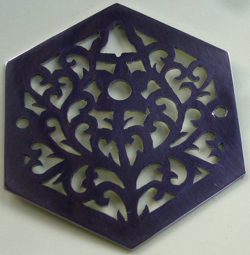
Because I made the bellpush fretwork before I started this blog, I thought I would take a step back and write a bit about how I did it. Here’s a picture of the finished item (remember it’s only 50mm wide):

Bell Push Top

What I didn’t do was to design it 1:1 with paper and a pencil. Given my limited artistic ability and the level of fine detail involved, using computer aided design software saved me a lot of time and almost certainly led to a better end result. I could zoom in and out, automatically turn wonky hand-drawn curves into nice smooth ones, repeatedly draw and erase (without leaving smudgy marks each time), undo, redo, tweak, retweak, and basically fiddle with the design for hours on end until I felt it was good enough to hit ‘print’. That’s my little secret: I’m not very good at freehand drawing (I wish I was), but if you’re patient enough CAD lets you keep on making hundreds of tiny incremental improvements until you finish up with something that looks pretty good. In theory also I could go from a vector drawing to a control program for a CNC tool like a laser cutter, which is something I want to try in the future, though this project was about learning to cut an end by hand.

The software I used is an open source vector drawing program called Inkscape. I’m using a snapshot of the current development version for two reasons: it has a couple of whizzy new features that make it easier to do this kind of design, and it finally runs natively on Mac OS X rather than via the rather clunky X11 interface. The two new features are both path effects: spiro spline and power stroke (stupid name). Spiro spline basically makes it easy to draw really smooth curves. Power stroke lets you draw variable width lines (you can later convert a power stroke into an outline path – i.e. two curves that define the edges of the power stroke line; unfortunately that’s a one-way conversion). Rather than me spend a few hundred words attempting to explain more clearly why the combination of these two features is really useful for drawing the scrolly shapes you find in a Victorian-style concertina end, take a look at this video. (Incidentally, he would have been better off using the Path->Union command at the end to combine multiple powerstrokes into a single path.)

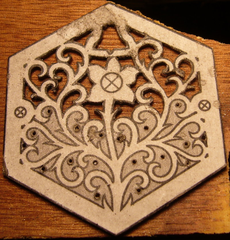
It took me three attempts to come up with a design I was happy with. Here are the three versions side by side:

top1 top2 top3

I spent a lot of time studying pictures of vintage concertina ends between attempts 2 and 3: I could tell my version looked wrong but it took a lot of analysis before I figured out exactly why and how to fix it. Something you might notice if you look closely is that in the first two the right and left hand sides are almost exact mirror images of each other. In the third one there are many very small differences between the two sides – this asymmetry, I found, makes the design look far more organic.

If you carefully compare the final design to the photo above, you’ll spot where I made a mistake with the saw in one place. I carefully tweaked the design to work around the mistake and it almost looks like I did it on purpose now!

Hand piercing a stainless steel concertina-style bell push

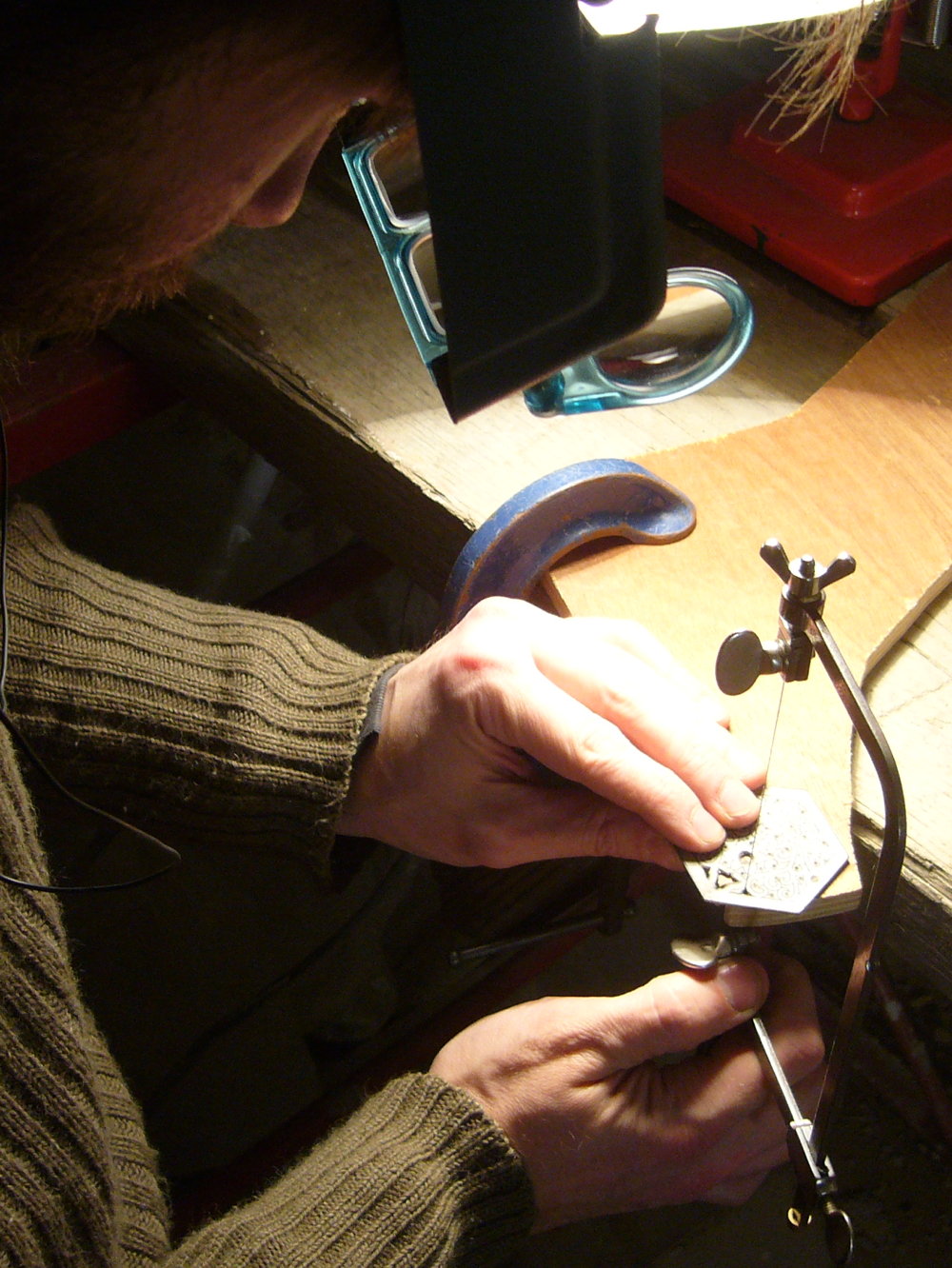
I cut the end by hand with a jeweller’s piercing saw, following a paper template glued to a piece of 1mm stainless steel. I used stainless because the bell push needs to be weather resistant – metal concertina ends are more commonly made of nickel-silver AKA German silver, which is actually a type of brass and is much easier to cut, though it would quickly tarnish outdoors. The biggest mistake I made was putting wax polish on the paper – I thought it would lubricate the saw blade and save me having to keep manually waxing the blade. Bad idea. The sawing generated a very fine black dust which stuck to the waxy paper and smudged it so badly that eventually I couldn’t see the lines clearly (hence the mistake mentioned above, caused by carrying on cutting where I thought there was supposed to be a line). After that mistake I printed out and glued a new template on top of the smudged one – very tricky to get the two perfectly registered – but then I had lots of problems with the bottom, waxy layer coming unstuck from the metal when I was cutting the points of the scrolls, hence why many of the points are slightly misshapen.

halfway

Another problem I ran into was blunting and breaking 1mm drill bits because I centre-punched where I wanted the holes to go, which work-hardened the stainless enough to cause my HSS drill bits to rub and go blunt instead of cutting. I switched to solid carbide bits (actually re-sharpened PCB drilling bits from eBay, which are good and surprisingly cheap). They cut through the work-hardened stainless OK, but I broke several of them because they tend to snatch as they break through the back of the work. Carbide is so brittle and delicate that the bits just instantly snap when that happens. In hindsight a better solution might be: a. mark the drill points using a centre drill or a tri-cornered centre punch and a very light tap to avoid work hardening the material, b. drill on top of a sacrificial piece of brass or aluminium to reduce the likelihood of snatching on break-through. I could also try using good quality cobalt bits instead of carbide.

The final problem I encountered was that of blunting and breaking jeweller’s saw blades. I must have gone through two or three dozen of them. I’m talking about very fine blades here – the teeth are so small that you can barely see them with the naked eye. They need to be small so you can cut the tiny details and tight curves inside the piercings. I started out using a highly-regarded brand that I have had success with in the past when cutting silver and brass, but they turned out to be not hard enough for stainless – they tend to go dull in one or two strokes. I found another brand that stays usably sharp for a bit longer (perhaps two piercings), but it’s still extremely easy to snag the blade in the cut and snap them because they are so tiny and delicate. It’s also very hard to follow a line closely with a dull blade because it tends to want to drift off in one direction or the other depending on which side happens to be sharper. One trick I might try in future is cutting out the bulk of each piercing out with a thicker, more robust blade, then going back later and doing the inner points and other details with a fine blade.

Fiddly Fretwork Read More »

Pint-size Printing Press

Here is my new toy essential concertina-making workshop tool (mug of tea is for scale):

adana1

adana2

It’s a little Adana High-Speed No.1 (also known as a HS1 or 3×2)  self-inking platen printing press, possibly dating back to the 1930s. I plan to use it to print decorative bellows papers and maker’s labels, and possibly also stationery and marketing materials – compliments slips, business cards, bookmarks, beer mats, etc. I could perhaps even take a few small commissions as a sideline (wedding invitations and the like!). The maximum size of forme you can fit in the bed is 3 3/4″ x 2 5/16″ (95 x 59mm), though obviously the paper can be a little bigger than that if the design has margins around the edge. I got it cheap because it looks a bit tatty and it’s missing several parts, many of which are no longer made.

Some of you are probably wondering at this point, “why bother?” I much prefer the appearance of Letterpress printing over modern laser or offset printing because the type makes a 3D impression in the paper (you can also use proper metallic gold or silver ink, which you can’t do with a laser). It’s almost certainly also the method that was used on original Victorian concertinas. Although there are still a handful of commercial letterpress printers around who would probably be willing to print my designs for a fee, I want to do the printing myself on a machine in my own workshop with plates I’ve designed and made myself, for the same reasons that I’m planning to make all the other parts of the concertina myself.

Luckily you can download the original user manual for free. It is ‘arrestingly written in a non-technical style.’

printing_made_easy

From these instructions I gather the way you use it is to place an arrangement of (missing) movable metal type and furniture called a forme in a (missing) chase or clamp it directly into the bed, use a (missing) hand roller to transfer some ink onto the (missing) inking disk, then move the handle most of the way down and back up to pick up some ink on the (missing) pair of inking rollers and transfer it onto the face of the type. Next you place your piece of paper or card on the (missing) tympan (which is held to the platen by the (missing) tympan clips), lining the bottom edge up against the (missing) lay gauge. Finally you push the handle all the way down to press the paper onto the type. When you release the handle the (missing) spring-loaded gripper finger pulls the paper off the type.

adana3

I’m not bothered about the fact that it didn’t come with any metal type, furniture, chases, quoins, etc. because I’m instead planning to make my own printing plates after designing them on a computer. I have a few different ideas for ways to make the plates. The most obvious one is to use sheets of photo-sensitive polymer that are designed for the purpose (I already have a UV exposure box for PCB photo-etching); the main drawback with them seems to be that they aren’t super robust and they have a limited shelf life; perhaps a few years at best. For one-off print runs that would be fine. I suppose it wouldn’t be too much of a hardship to make new polymer plates every couple of years.

Alternatively I could use the same techniques that I use for PCB etching to make etched brass printing plates (using spray-on photo-resist). If I can get that to work and produce clean sharp edges, brass is hard enough that the plates ought to last pretty much forever as long as I don’t abuse them. Another idea I’m considering is to cut brass or aluminium plates on the CNC milling machine with a small vee engraving bit. That ought to produce excellent clean results, although it would probably be quite a slow process and any sharp internal corners might require cutting by hand with a fine graver. It might not be trivial to convert the design into G-code either. I’ve even considered using the mill to engrave a positive “matrix” into a piece of aluminium and use that to cast plates in type metal. One potential advantage of this method is I could mill a single matrix for a bellows paper or logo design and then cast as many copies of it as will fit into the bed of the press.

I’ve had to buy a new pair of inking rollers because, although I probably could have made the mechanical parts, I don’t have any practical way of casting the special soft rubber compound onto them. Luckily they are still made, though a pair cost me more than I paid for the entire machine!

I’ve also ordered a cheap soft rubber hand roller made by “Speedball” (isn’t that slang for an illegal substance?) to ‘mill’ the ink (work it until it’s totally smooth) on a sheet of glass and transfer it to the inking disk.

The inking disk shouldn’t be too hard to make. I’m planning to cut it from 3mm engraver’s brass sheet with a scroll saw, round off the edges, and braze a steel hub to the bottom. I haven’t yet decided how to make the ratchet on the bottom that rotates it to evenly distribute the ink, but I have a couple of ideas. The simplest way seems to be a circle of holes drilled in another disk soldered/glued to the bottom. The point of the pawl is a bit worn, but interestingly it looks like it was made to be reversible when the first point wears out:

adana4

The tympan clips will be trivial to make from stainless steel sheet. The tympan/packing is a bit of mystery to me – it would probably be easy to make if I knew exactly what to make it from (it seems to be some combination of card and paper). The purpose of it is to provide a soft surface between the paper and the platen so that the type makes a visible impression in the paper and isn’t damaged by being forced hard against the metal platen. More research and probably experimentation needed.

The lay gauge will probably not be too difficult to make from a strip of brass or aluminium and some small screws and wing nuts, though I don’t fully understand the illustrations of it in the manual – it has various cutouts and holes in it that I haven’t yet worked out the purpose of.

The most difficult replacement part to make looks like being the gripper arm and gripper finger. This is the part that holds the paper against the tympan so that when you release the handle the paper doesn’t remain stuck to the type (if it did, the inking rollers would probably run over the back of it before you had a chance to manually remove it). It needs to be adjustable for different sizes and thicknesses of paper and there needs to be a long spring so it can easily be lifted up to replace the paper. I’ll also need to track down a nut that fits the shaft so that I can attach it to the machine (almost certainly won’t be metric; possibly 2BA or similar).

Pint-size Printing Press Read More »

Steppers

The stepper motors have arrived that I’m going to use to convert my Taig Micro-Mill to CNC.

steppers

It’s hard to explain how exciting this is. I’ve dreamed of owning a CNC machine tool for probably twenty years and yet somehow never got around to building one. I bought the Taig about a decade ago for another project with the intention of fitting it with DC motors and encoders and building my own servo controllers (in hindsight that was a bit of a silly idea considering steppers are relatively cheap and work OK on a machine as small as the Taig). I got as far as buying the motors, encoders, pulleys and toothed belts, and a large block of aluminium that I was going to machine the mountings from, before the project ground to a halt. There are some photos on my old website of the mill when I first received it. I have used it occasionally as a manual mill but what I really want is to be able to use it to machine complicated parts under automatic control.

The motors are bigger than I expected, and I went for the small end of the range people tend to put on this machine. There are a couple of different theories on stepper motor sizing for the Taig mill: 1. use small motors and keep everything well adjusted and lubricated so you don’t need lots of torque. 2. use big motors so you have lots of torque in reserve and it doesn’t matter so much if the leadscrews and slides get a bit stiff. The advantage of the smaller motor option, as well as lower cost (both in terms of the motors and the electronics to drive them), weight, power consumption, and heat generated, is that smaller motors have lower winding inductance and armature mass. Lower inductance means the torque doesn’t drop off as rapidly as the speed increases; lower mass means they can accelerate and decelerate quicker. I’ve read people advocating both paths and claiming to get better results with small/large stepper motors, but the smaller, nimbler option appealed to my sensibilities more (as somebody who is happy driving a small, light car with a 48Bhp engine).


Steppers Read More »

Clico Swiss Bench Shear

Here’s another lovely vintage tool; one that almost certainly will get used in my concertina production. It’s a small Swiss-made bench shear of a design that I have never seen before. One of the blades is a helical shape (that must have been pretty tricky to make!), and as you rotate it the shearing point slides along the fixed straight blade. The maker’s stamp appears to say ‘Clico’ but other than that I know very little about it. It’s quite small and very precisely made; I suspect it was probably intended for jewellery or clockmaking. It was a little bit pricey for a second hand tool (about the same as a new Chinese-made bench shear of more conventional design), but it’s such a lovely thing and works so well that I regard it as a bargain. As long as I don’t abuse it and hone the edges occasionally, it should outlast me. When I got it the blades were quite blunt but it still cut surprisingly well. I sharpened them last night and it now cuts really cleanly with more control and much less effort than a pair of hand shears.

shear1

The state the edges were in before sharpening:

shear2

The unclear maker’s stamp. I think it says “Clico”. The number doesn’t seem to refer to a patent (too short). Perhaps it is a serial number.

shear3


A brief video showing how it works (I would normally use two hands but one was holding the camera):

Clico Swiss Bench Shear Read More »