No. 1: Brun Part 2: End Plates and Hand Rails
Apologies for the long delay since part 1 of this short series about how I built my first instrument, Holden Concertinas No. 1, a small rectangular 30 button Hayden Duet. I have now finished the instrument and begun design and tooling work on No. 2, which will be a more conventional hexagonal 30 button Anglo.
First a caveat. This was my first instrument, built from scratch without plans or instructions, in some cases involving materials and techniques that were new to me, not under the direct guidance of an expert (though several experienced makers offered useful advice when I had a specific question). I was constantly figuring out how to do things and building tools as I went along, and sometimes my ideas didn’t work out perfectly, or by doing a process one way I learned something that helped me to see a better way to do it. In some cases I was limited by the tools available to me, and I made a point of making everything myself in my own workshop (apart from the stainless steel screws). I think overall the instrument turned out remarkably well, with a few mainly cosmetic flaws, but there is certainly plenty of room for improvement when I build No. 2. This article is the story of how I did it on my first attempt and what I learned along the way, not a definitive guide to building one yourself.
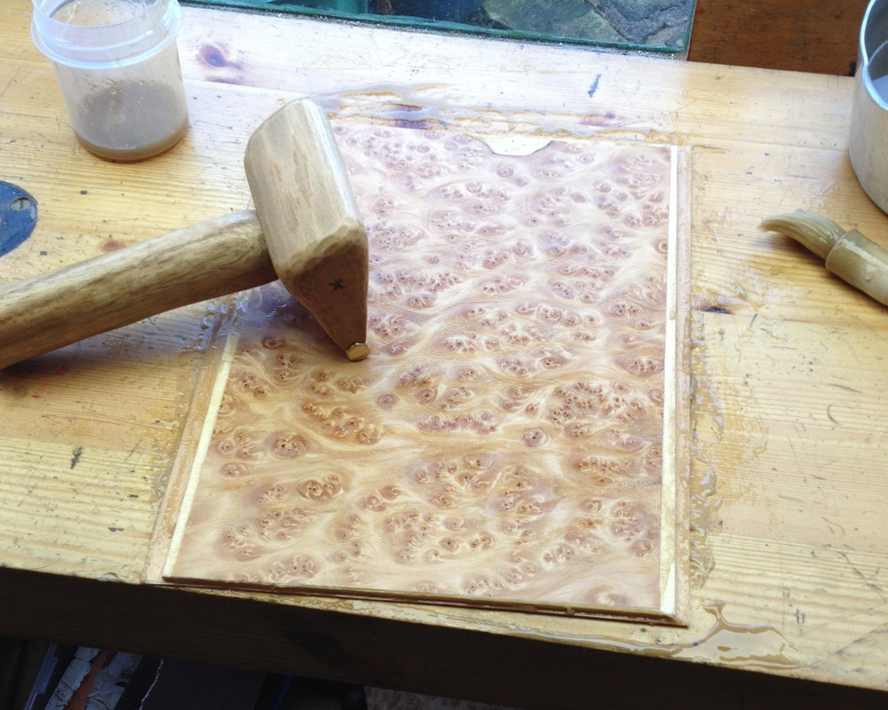
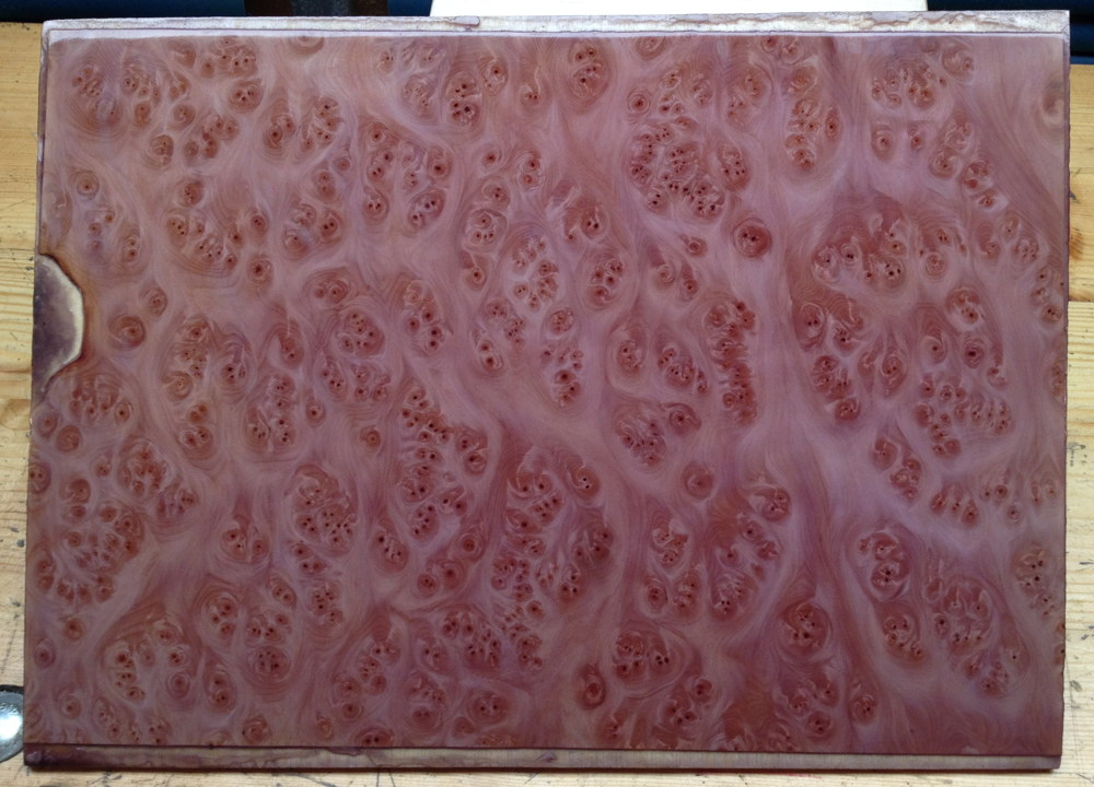
The wooden end plates were made from 3mm birch plywood (the best quality I could find), hammer-veneered using hot hide glue and a veneer hammer I made myself from oak with a brass blade. The top veneer is a very pretty fir burr (or burl for the Americans), with a cheaper beech veneer on the bottom (you always veneer both sides of a board at the same time to reduce warping; in this case it also helped to thicken and strengthen the board). Unfortunately on the finished instrument the beauty of the pattern is rather hidden by all the piercings, buttons and handles, though there are areas where it is still visible. I dried the board between paper in a simple press for a week or so. After taking it out, it warped slightly, but it was flexible enough that screwing the plates to the rigid end boxes pulled them flat again, and in fact I now find that after a few months being held flat by the boxes, they remain flat when I take them off.
I decided to try French polishing the instrument, and I thought it would be easier to polish the board before I cut out the fretwork (in hindsight this was probably a mistake). This was my first time using the technique. It took a very long time, I made a bunch of mistakes, and the results weren’t entirely satisfactory. I learned a great deal, though, and I’m sure the next one will be better. One of the problems I ran into is that in the UK the sort of alcohol you can buy in a DIY shop (methylated spirits) has a small amount of poison and purple dye added to it to prevent people drinking it. It turns out that if you dissolve blonde (clear) shellac in ordinary purple meths, the dye doesn’t evaporate along with the alcohol, it stays in the finish. The thicker the finish, the deeper the purple, and due to inexperience I accidentally made the finish on the end plates way too thick. Funnily enough the change was so gradual I barely noticed it happening, until I happened to place the polished board next to an offcut of the original veneer! For my second instrument I am planning to try dissolving the shellac in clear ethyl alcohol that I found being sold online for medicinal purposes; it’s quite a lot more expensive than meths per litre, but I don’t need huge amounts of it to polish a concertina.
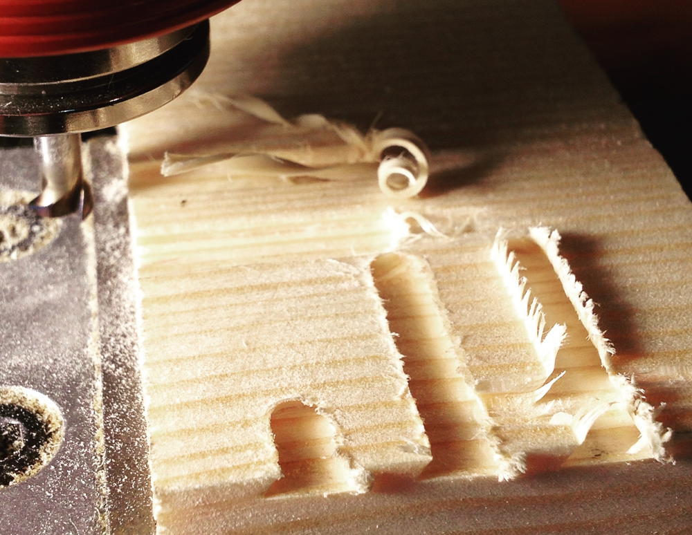
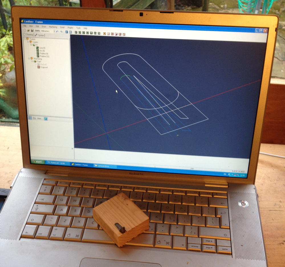
Next I cut the board into two pieces and stuck my cutting templates to them, then drilled all the holes on the CNC mill. Ignore the fact that the mounting holes appear to be in the wrong places – there was a reason I had to do that, which I’ll talk about in the next instalment. The fretwork design is my own, inspired by Indian mandala designs. Circles within circles within a circle within a square. It may not be to everybody’s taste but I am rather proud of it. The space below the fretwork was left empty because I knew the handles needed to go down there, but I didn’t drill any mounting holes at this stage because I hadn’t yet figured out exactly how or where they were going to attach.
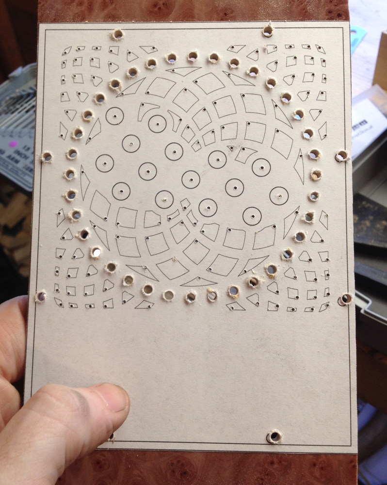
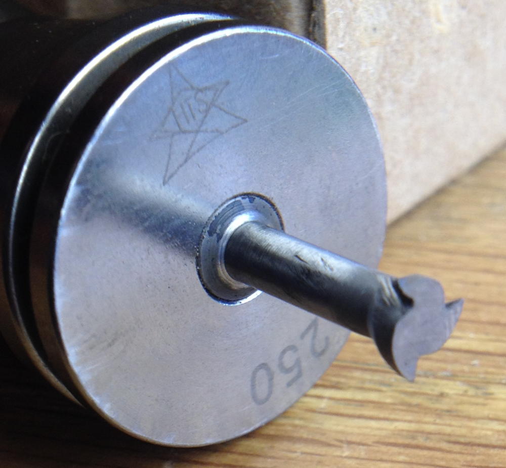
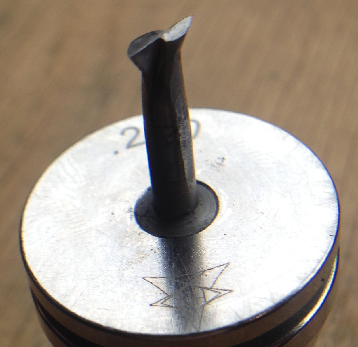
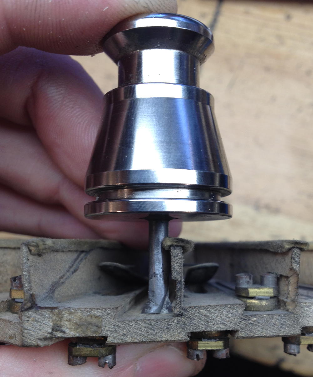
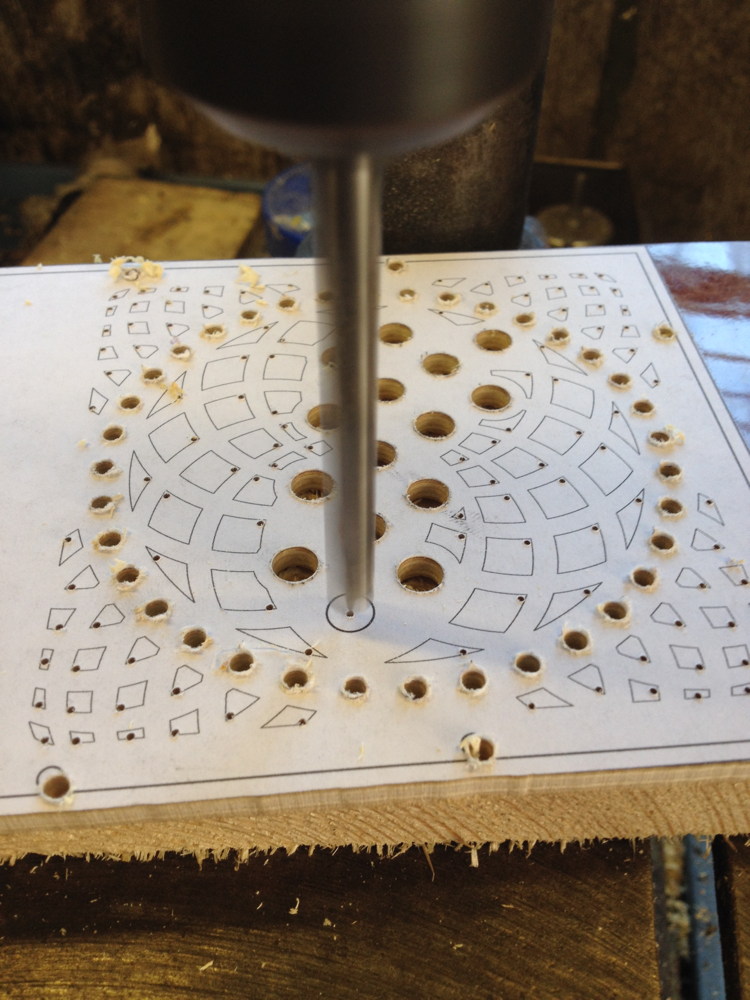
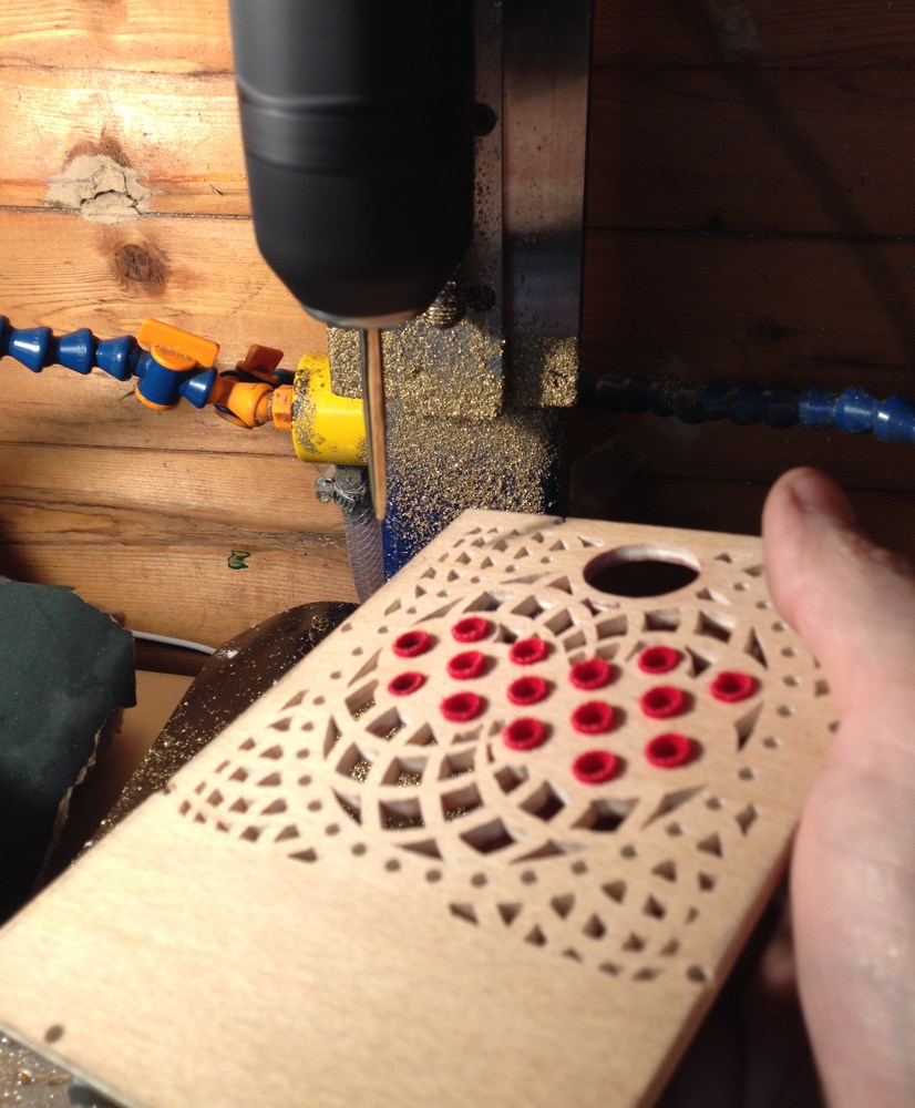
I couldn’t drill the button holes to final diameter on the CNC mill because the drill bit I had was too long for the Z height of the machine, so I instead drilled small pilot holes and then manually enlarged them on the pillar drill. I was a bit worried the face veneer would splinter out when the drill bit entered the board, but I used a sharp brad point bit, fed it in gently, and they all turned out perfectly.
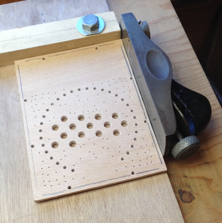
The end plates fit into rebates in the end boxes (in order to hide the cut edge of the plywood), which meant I had to do some fiddly manual trimming of the edges using a block plane and shooting board to get them to fit in perfectly without a gap.
I cut the fretwork by hand with a vintage fretsaw. It may look tedious but I actually really enjoy this part of the job!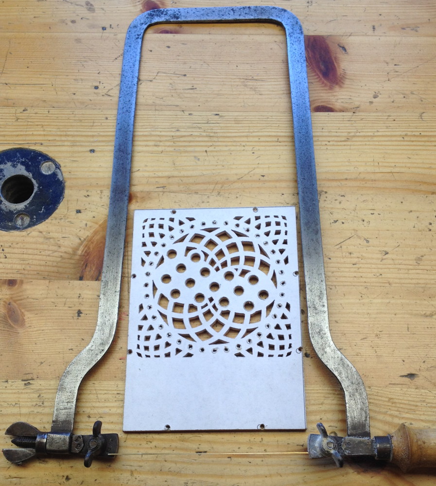
Here is a little video clip of me working on the piercing while listening to Lady Maisery on the stereo (you have to click it again to stop it playing or it will automatically repeat):
https://www.instagram.com/p/BOo5Y5mACys/
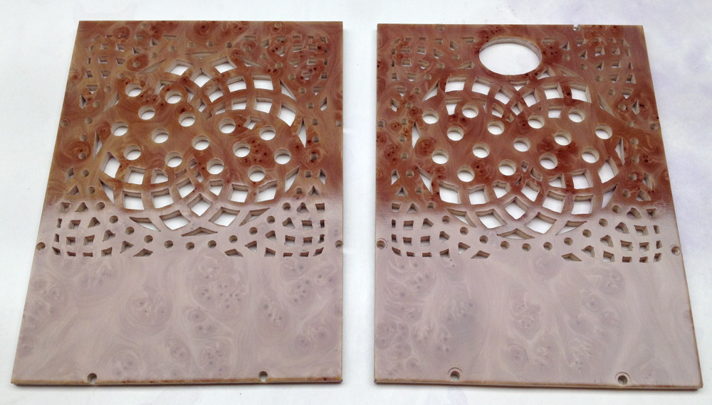
After I’d finished piercing and peeled the sticky paper templates off, I found that the thick shellac finish had gone rough, so I decided to sand it down and try polishing it again. 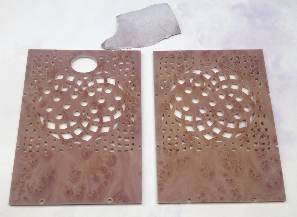
The result was a significant improvement, though not totally perfect. In hindsight I probably should have kept going, taken all the shellac off, and completely started from scratch, but I was loath to do that because of the many hours it had taken me to build it up in the first place.
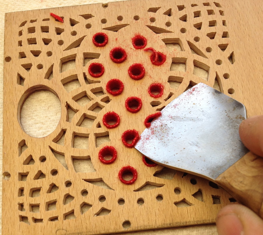
I reamed the button holes out a little from the back using a taper hand reamer, then glued in bushes made from 0.85mm piano bushing cloth. This is a fiddly job that is difficult to do neatly, though I found that I got better and quicker at it with practice. Here’s a quick video clip showing how I did it using hot hide glue. I’m working from the back but aiming to get the front edge of the cloth to sit flush with the front face of the end plate because it’s not possible to neatly trim it flush afterwards.
https://www.instagram.com/p/BO_-jBWAfd_/
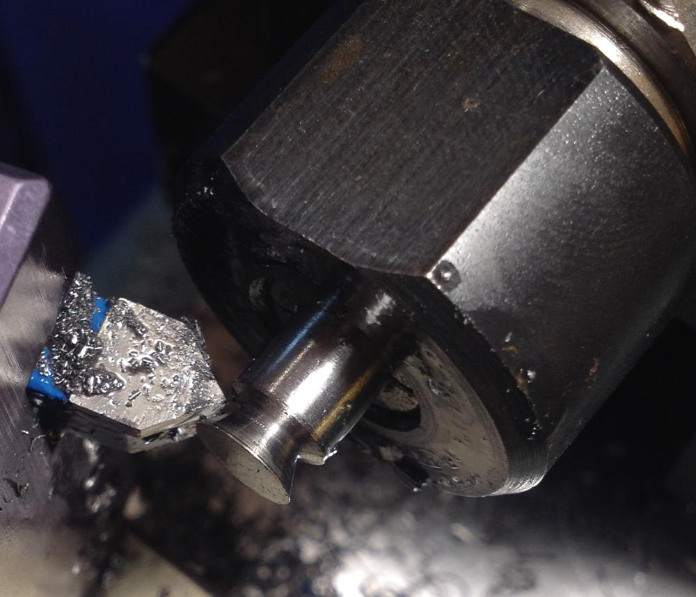
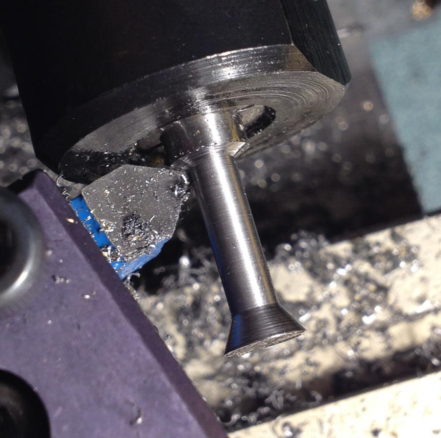
After the glue had dried, the buttons fit in the bushes but there was too much friction, so I turned a tapered polished brass rod the same size as the buttons and used it in the milling machine spindle at 10,000 RPM to burnish the inside of each bush. This had almost no effect! Second attempt, I made another tapered rod that was slightly larger than the buttons, and waggled it around a bit in each hole. This made the holes just right so the buttons went up and down with hardly any friction or noise. After a couple of weeks I found that a few of the buttons were sticking because the bushing cloth had bounced back, so I repeated the burnishing operation. This second burnishing seems to have done the trick; months later the buttons are still working smoothly.
The extra bit of felt sticking out of the back of each button hole was in some cases interfering with the cross holes in the buttons and preventing them closing fully, so I trimmed them all flush with the back of the plate.
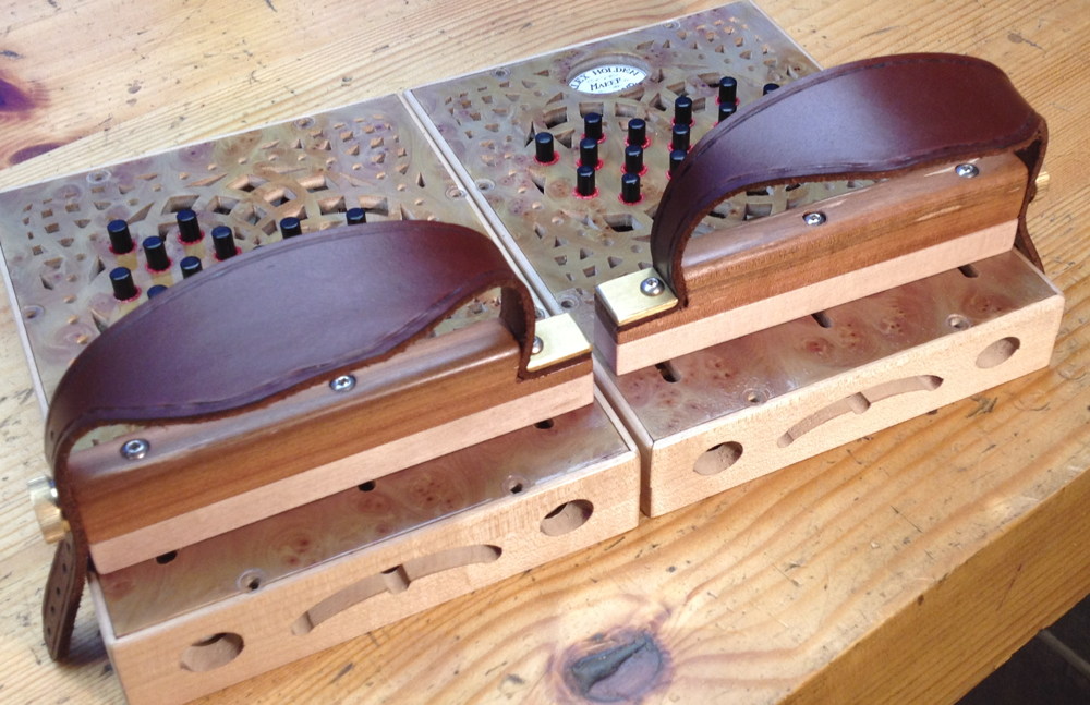
On to the hand rails (I know I’m skipping over the casework and action; I’ll cover those in another instalment). I had an idea to try making more ergonomic handles and spent a while experimenting with a set. Unfortunately they didn’t really work out for various reasons that are outside the scope of this article, but I’ll include a couple of pictures because I think they looked rather pretty.
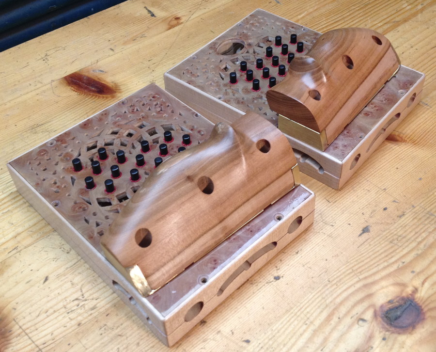
Back to the drawing board, I decided to make a pair of simple Anglo-style hand rails, but with the ability to adjust them backwards and forwards, and a spacer block that allows the height to be raised or lowered.
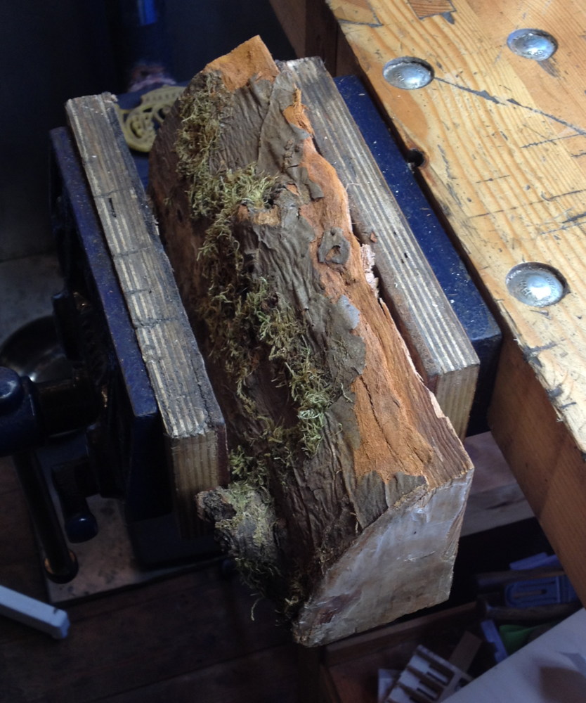
The top parts of the rails were made from slightly spalted apple wood from a tree that was taken down in my best friend’s orchard:
The spacers below the main rails were made from contrasting sycamore wood:
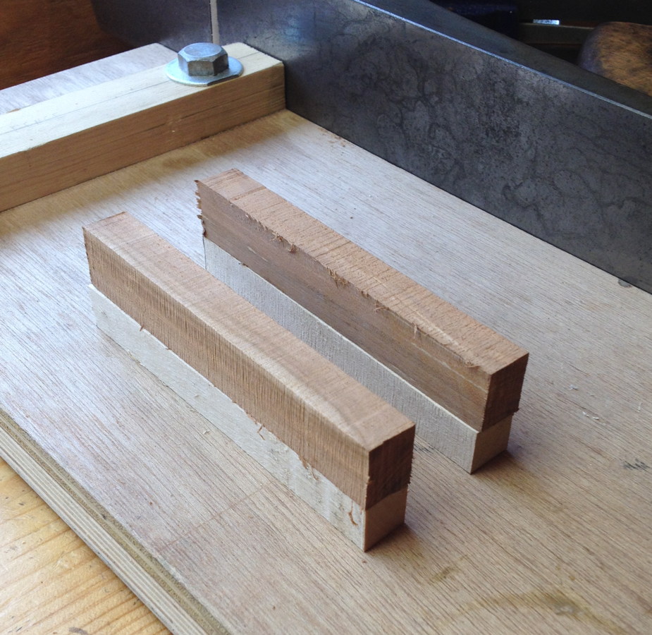
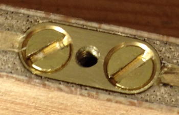
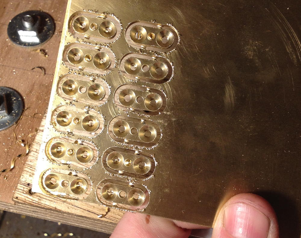
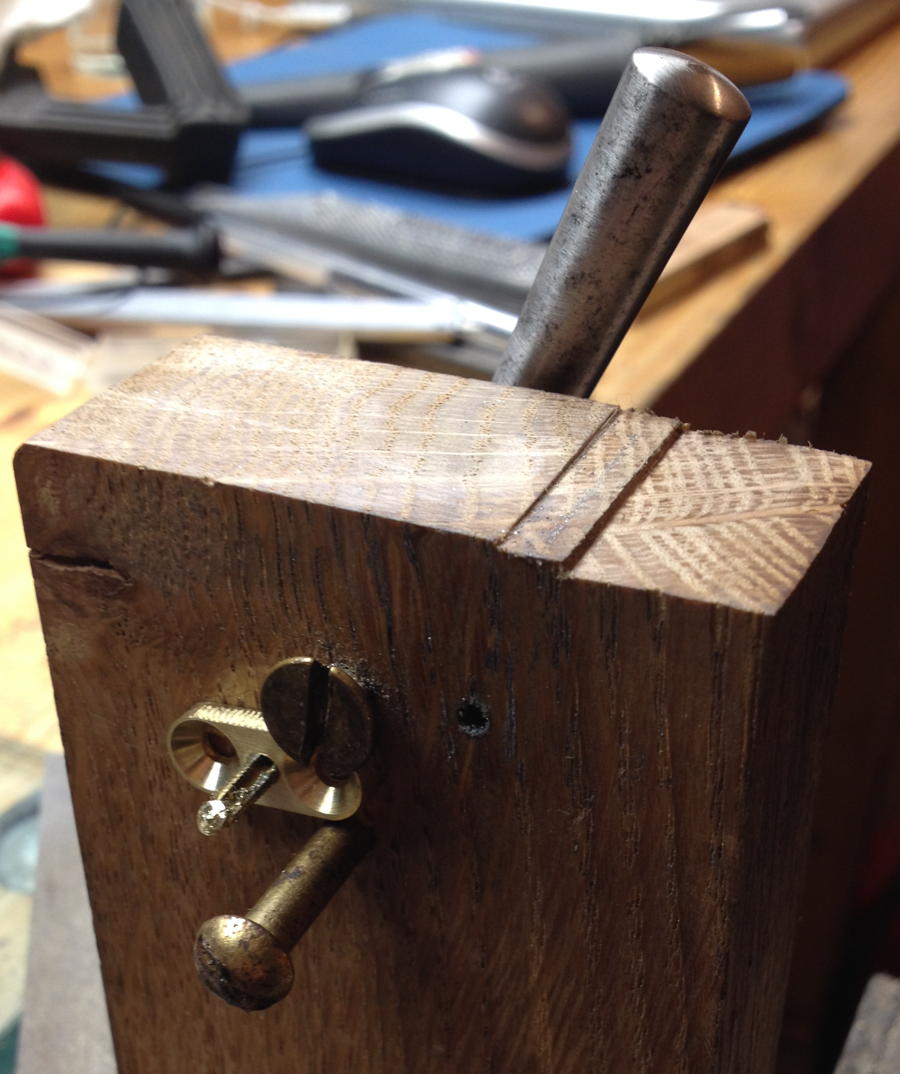
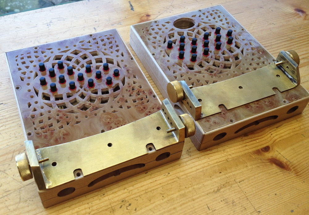
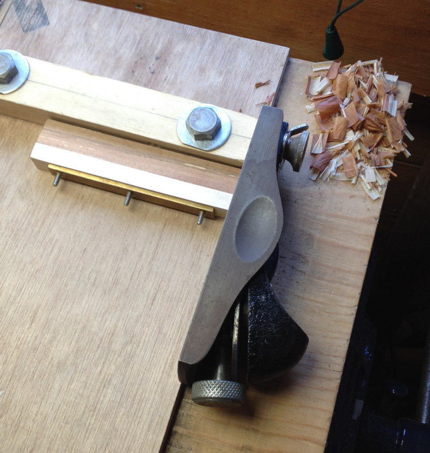
While planing the two pieces to match each other, I clamped them together using the same bolts and captive nut plates that would later be used to hold them onto the end plates:
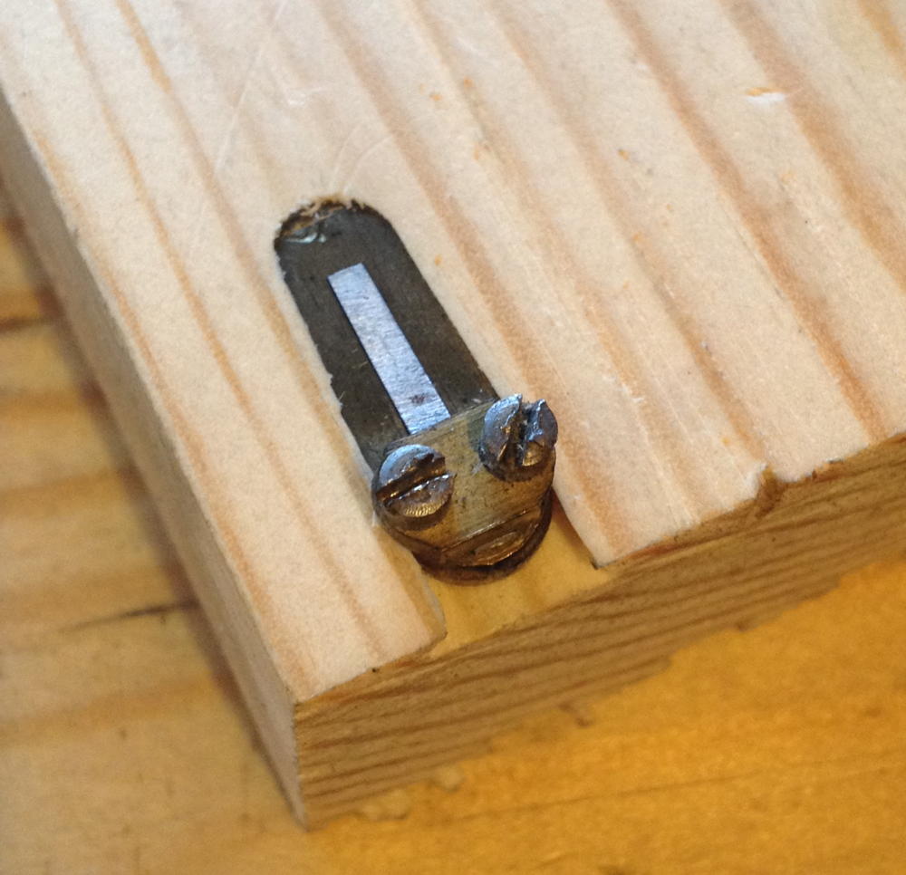
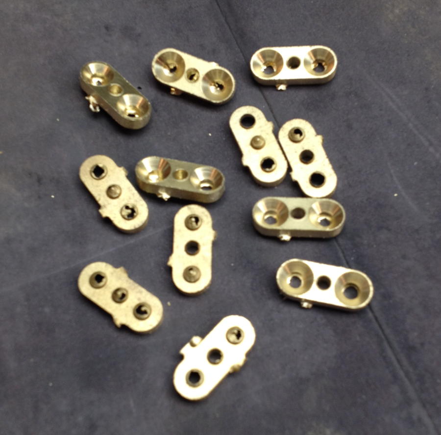
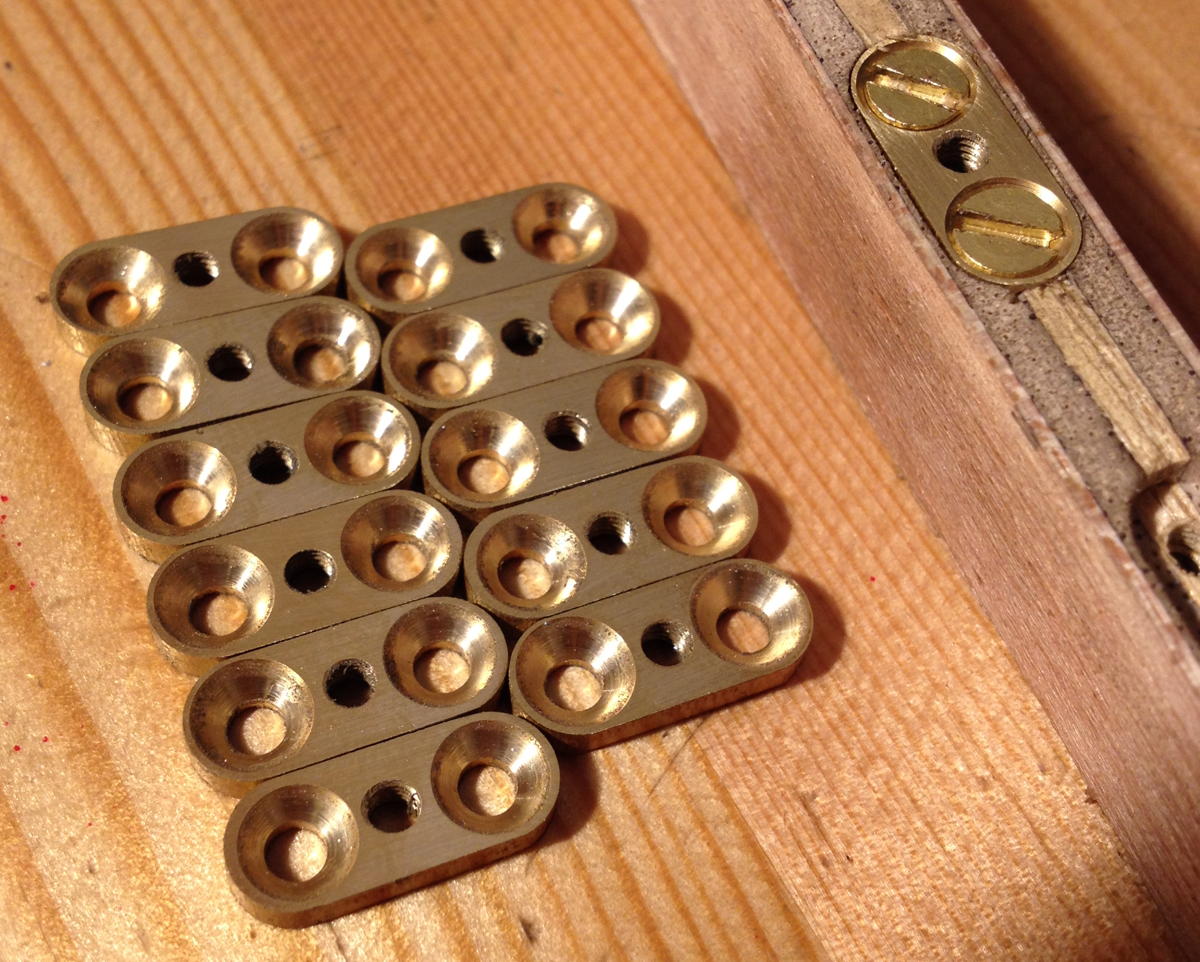
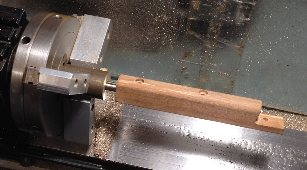
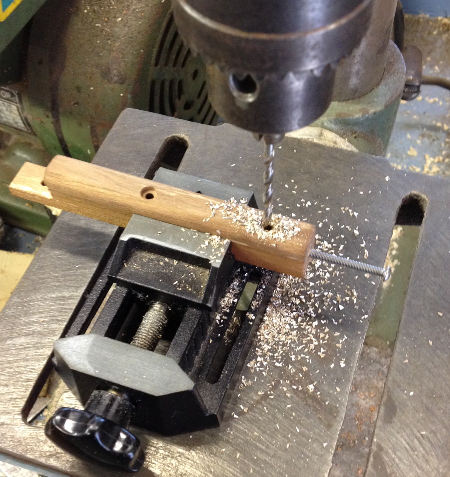
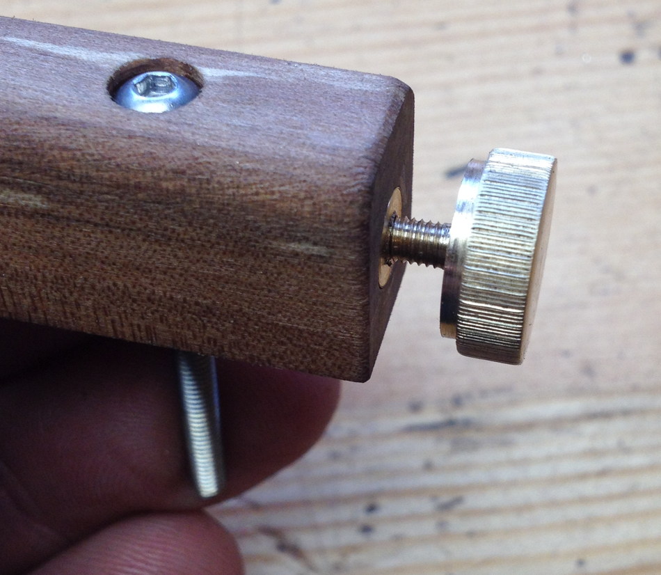
Because the handle could be adjusted back and forth, it didn’t make sense to attach the strap to a fixed point on the side of the action box, which meant I instead had to put the strap clamp screw on the end of the rail. This meant making a captive nut that fit into the end of the rail, and was held very securely by one of the main attachment bolts passing through a cross hole drilled through the nut:
This wasn’t my first attempt at making thumb screws: the earlier ergonomic handles had four larger-diameter screws. I think the final ones I put on the instrument turned out reasonably well, though the knurling isn’t as neat as I’d like due to the knurling tool I bought being a bit too sloppy. I am planning to make a stronger tool with finer wheels before I knurl the screws for the second instrument.
I lightly French-polished the handles and cut the straps from 2mm full grain veg tanned calf skin. I think the shape worked out OK, though I did the decorative creasing around the edge using a tool improvised from an old soldering iron and it went a bit wonky in the curved areas (I’m planning to get or make a better creasing iron before I make the next set of straps).
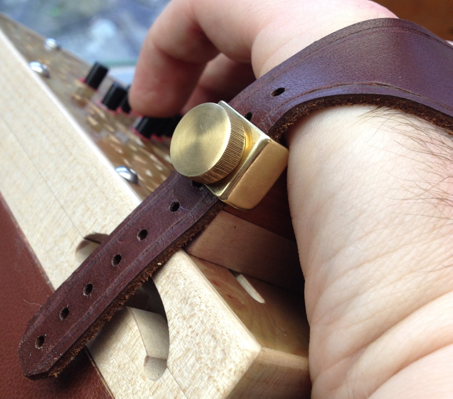
I found that after playing the instrument for a few minutes the thumb screws started to unscrew themselves. The solution came in a photo I found of a Dipper instrument that had the thumb screws in the same location: a clamp plate like a large washer that is bent around the end of the rail. This prevents the screw turning when the strap moves and looks quite snazzy too! I have since seen exactly the same arrangement on instruments made by Geoffrey Crabb. I put the two bends in the clamp by clamping it in the middle of a toolmakers’ clamp that happened to be the same width as the rail (1/2″).
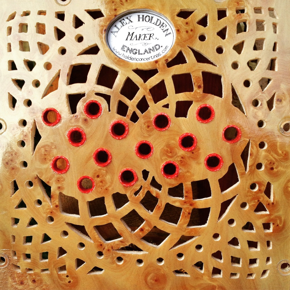
The final touch on the end plates was to add my maker’s label. The design was hand lettered by my talented friend, Oliver Densham, in a style inspired by the labels used on vintage Victorian instruments. I laser-printed it onto archival grade paper and sprayed it with a special protective lacquer intended for decoupage art, so it should hopefully last a long time.
![]()