I’ve been spending quite a bit of time recently working on my CNC milling machine and learning how to program it.
The main improvement I’ve made is to replace the spindle drive motor. The one that came with the machine was a 1/4HP single phase motor that ran at a fixed speed that gave me, on the top pulley ratio, something like 4000RPM at the spindle.
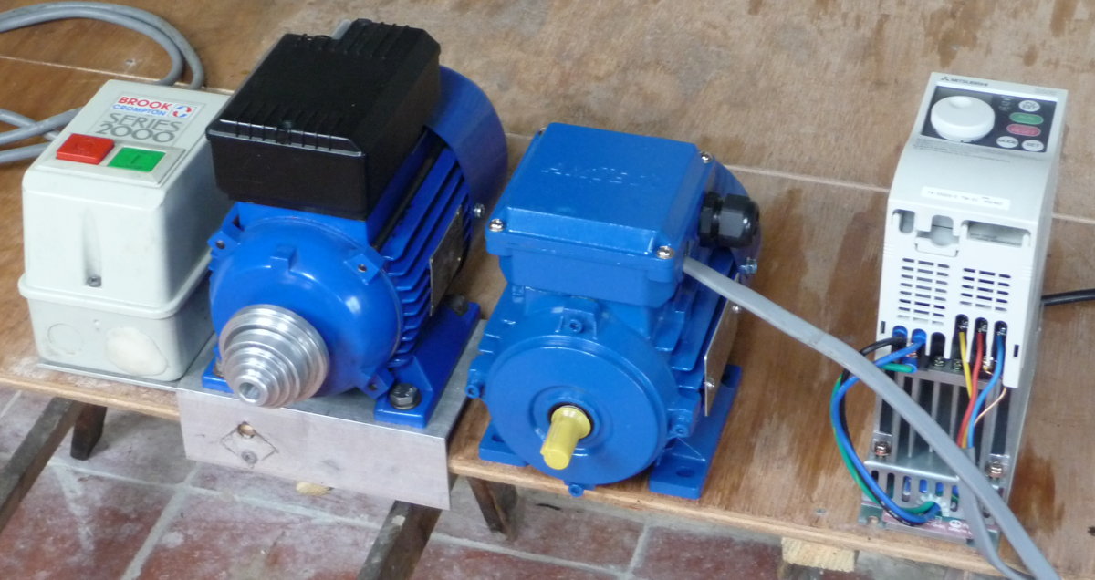
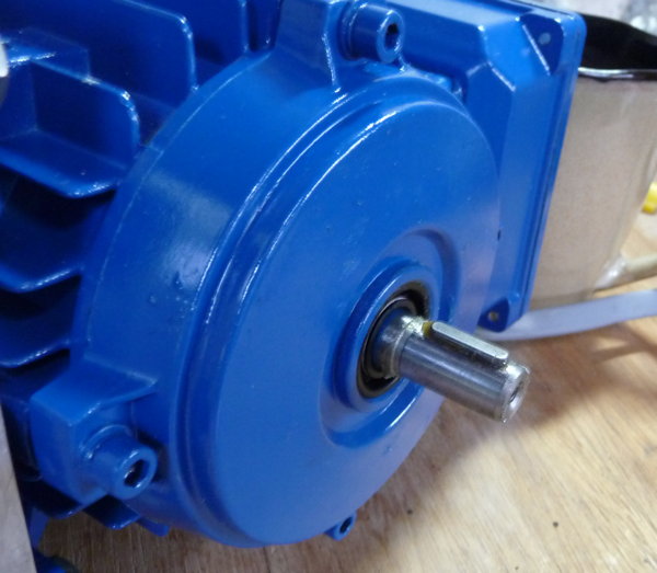
The new one is pretty much the same physical size and weight (maybe a little bit lighter) but it is a 1/3HP three phase motor that, paired with a used Mitsubishi Variable Frequency Drive (VFD) from eBay, can run at any speed from almost 0RPM up to higher than I’ve dared to take it (it’s comfortably fast enough to run the spindle at its rated maximum speed with the standard bearings: 10,000RPM). It’s a fully enclosed industrial induction motor, so it should be robust and have a long lifespan in the presence of dust and swarf. I’m surprised more people don’t go down this route to put a variable speed motor on their Taig mills; it seems almost ideal if you’re happy with the standard Taig spindle. Eventually I’ll probably put a similar setup on my lathe. The main drawback is that it’s fairly complicated to configure the VFD to get it to perform optimally.
The VFD replaces the contactor (the glorified on/off switch bolted to the old motor) and I won’t be mounting the VFD on the side of the new motor, so that has reduced the weight on my Z axis a bit more.
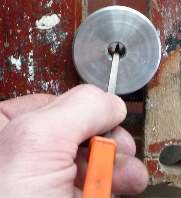
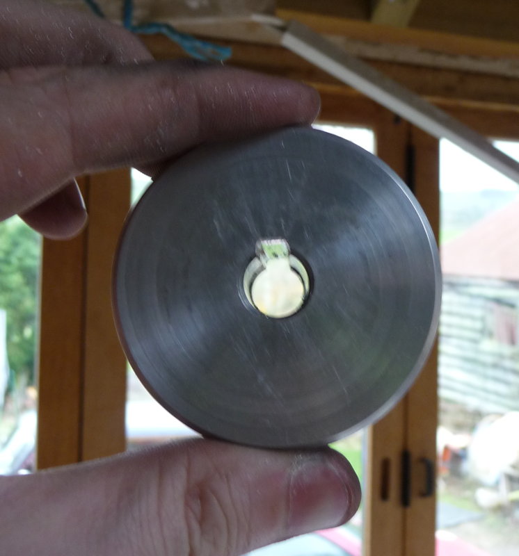
The drive shaft key had been removed from the old motor to avoid having to cut a keyway in the pulley (not me: it was like that when I bought it). Although I’ve never had a problem with it, that felt like a bit of a bodge so I used a square needle file to cut a keyway in the pulley for the new motor:
The VFD can take an analogue voltage input to set the speed, and the machine controller I’m using can output a PWM signal when the G-Code commands it to switch the spindle on, so at some point I’ll build an interface board to connect the two together. For the time being I’m just manually controlling the motor using the VFD’s front panel. I wrote a little Python script to figure out what pulley ratio and motor frequency to use to get a particular spindle speed.
If there’s anything in the new motor setup I’m not totally happy with, it’s the Gates miniature V belt drive. When it’s working well it’s adequate for the task, but the belts are stupidly expensive and seem to be quite easily damaged. After having a couple go bad recently, I have taken to slackening the motor mounting bolts and releasing the belt tension every time I change pulley ratios and when I’ve finished using the machine for the day.
The new motor did show up a problem with the CNC controller. It seems that VFDs put out electrical interference. Lots of it. I had previously found with the old motor that I would sometimes get a spurious E-stop input when I switched it on or off. With the VFD I could get them at any time the motor was running, and also the steppers sounded ‘lumpy’ and kept randomly stalling. I found that if the spindle motor was running while an axis was doing a rapid move and I picked up the VFD and moved it close to the CNC controller box, the stepper would inevitably stall. Conversely if I moved the VFD and controller as far away from each other as the cables would allow and placed a metal bucket over the VFD, the problem went away. The permanent cure turned out to be that I needed to connect the 0V rail of the Arduino in the controller to the chassis earth star point. Since then it’s been behaving itself.
I’ve fixed quite a few bugs in Handwheel and implemented a few new features, and it’s running pretty well for me now. I’ve been doing the development on an old dual-core Macbook Pro and my workshop machine is a quad-core Raspberry Pi 2, and it performs great on both of those. Handwheel is divided into several threads, structured in such a way that as long as your computer has at least two processor cores (ideally four), the overhead of updating the GUI shouldn’t slow down a file send. I decided to check that it worked OK on a standard (not overclocked) single-core Raspberry Pi 1: nope, the experience was dreadful because the rapid GUI updates were chewing up all the CPU and slowing the whole system to a crawl. Several hours of optimising later, the experience on the Pi 1 is now acceptable and faster machines like the Pi 2 are even snappier. I think it will run pretty well on the new super-cheap Pi Zero too, which has the same processor as the Pi 1 but is clocked something like 40% faster. I’m hoping to finally put out an initial public release over the Christmas break.
I also got side-tracked into working on a problem that was causing data corruption between the computer and the Arduino at 250000 baud: I tracked it down to the firmware on the Atmega 16U2 processor they use as a USB to Serial bridge, and came up with a fix.
I’ve started learning how to take a design and make it into a set of instructions to control the machine. This is called Computer Aided Machining, or CAM for short, not to be confused with Computer Aided Design (CAD), which is basically a way to do engineering drawings on a computer. There are a huge number of CAM programs available, with a wide range of capability and maturity at prices from free up to thousands of pounds per year. After quite a bit of research I settled on a program called CamBam, which seems to be the most capable option I could afford. Awkwardly, because it’s a Windows program and I’m a Mac user I ended up also buying a second hand Windows XP license and installing it on a virtual machine. A little bit clunky, but it seems to be working OK.
There’s a pretty steep learning curve to CAM, particularly as I haven’t got a great deal of experience or any formal training on manual milling machines. For example when milling manually I would guess at a spindle speed and depth of cut, then adjust the feed rate by gut feel based on the sound of the tool (and perhaps how much smoke/steam was coming off the cutting lubricant!). With CNC you calculate the parameters in advance, configure them in your CAM program, double and triple check everything, and hope you didn’t put a decimal point in the wrong place and accidentally command the machine to stab the end mill into the work at 500 miles per hour. Actually, I’ve found with my initial experiments with routing wood using carbide bits, the limiting factor in how fast I can cut is my machine’s top speed (1400 mm/min, 55″/min), which is set by how fast the Arduino running grbl can emit step pulses (30KHz). As a result I’ve been turning down the spindle speed to something like 5000-7000 RPM in order to get a decent chip load and avoid making a lot of dust and heat. It isn’t really a problem for what I’m doing with the machine, but I must admit the part of me that wants to optimise everything has been considering overclocking the CPU in the Arduino to increase the maximum pulse rate!
The first thing I milled under CNC control was to flatten the top of a plywood spoilboard I made that bolts to the bed of the machine and allows me to easily screw down work and to cut through it without damaging anything important (when it gets too chewed up I can re-surface it, and when it gets too thin I can glue a new piece of plywood on to build the height back up).
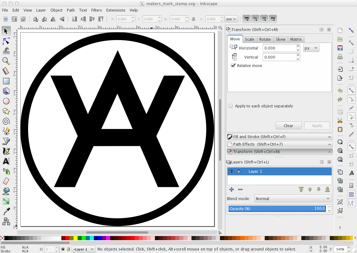
The second thing I made is a wooden stamp of my maker’s mark. I started out by designing it in Inkscape. It began as a Futura ‘A’, then I tweaked the proportions a bit and added the arms and the outer border:
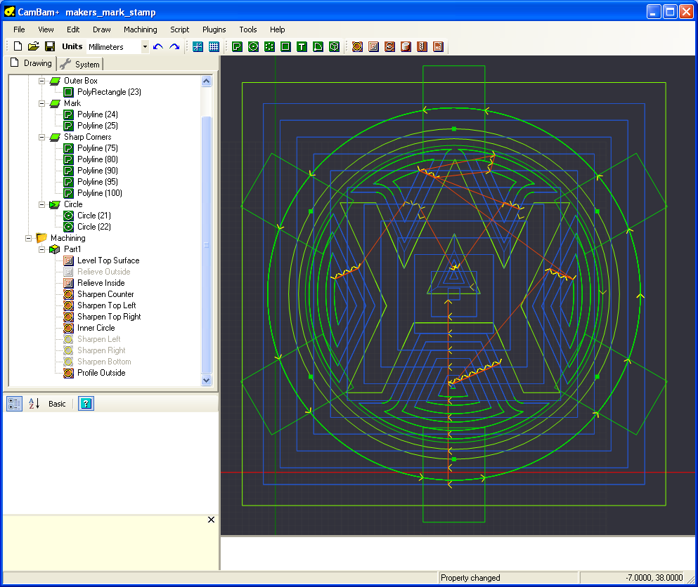
Next I exported it to DXF and imported it into CamBam. This screenshot shows the finished design including all the generated toolpaths. Figuring out how to do this is what took the bulk of the time spent on the project. Now I have a better idea what I’m doing I could do a second one fairly quickly:
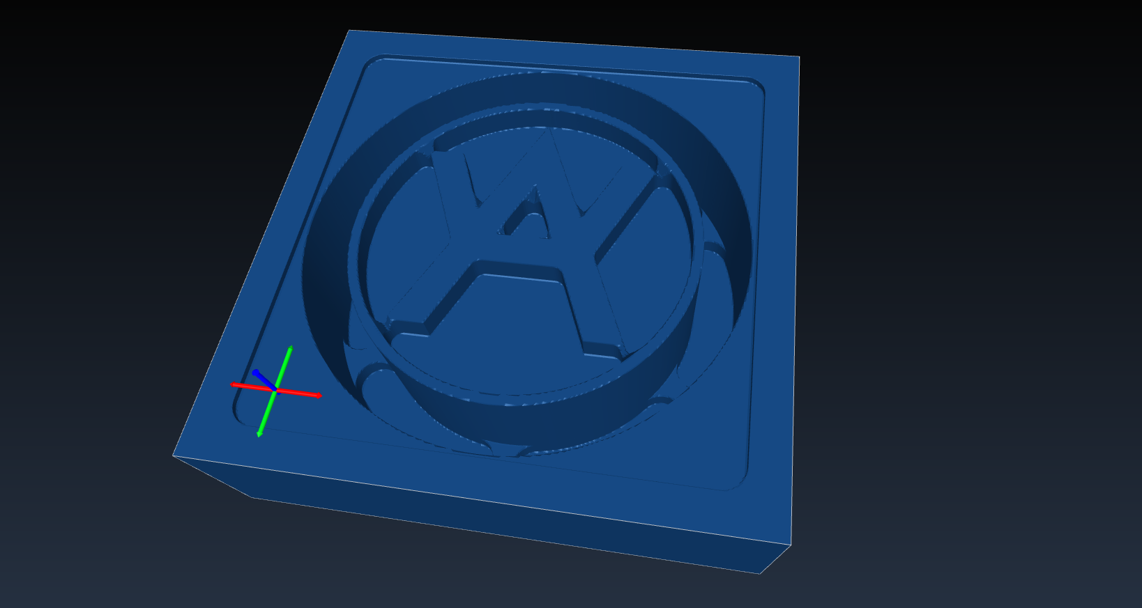
While developing the CamBam design, it was extremely useful to be able to be able to simulate what would happen if I was to machine the part. For this I used an open source program called CAMotics (formerly OpenSCAM). It’s still a little rough around the edges but I found it super useful. As soon as I actually make some money from CNC I’ll be sending a donation their way.
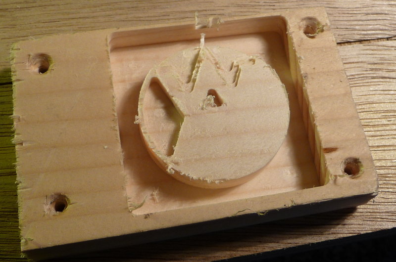
Before making the real part, I did a test run using some scrap pine. Good job I did, because it turned out I’d set the stepper motor acceleration parameters a bit too high and part way through the Y axis started losing steps:
After dropping the acceleration by 20% I completed a second, successful, test run, then made the real part from end-grain limewood:

I’m pretty pleased with the end result. The wood soaked up the ink like a sponge; in hindsight it might have been a good idea to seal it with a coat of shellac or something before using it.