
This instrument was a long term side-project that I finished off just in time for Christmas last year. It was an unusual project for me because I didn’t make the reeds (they are Hohner accordion bass reeds) or the bellows (they were reclaimed from a large Lachenal baritone Maccann), and it only has buttons and fretwork on one side. It was also the largest instrument I had built up to that point, and had the lowest bottom note (F1, 43.65 Hz).
Button Layout
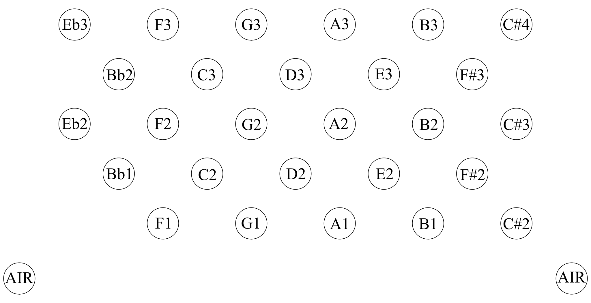
I put quite a bit of thought into the button layout. The bottom note (F1) was determined by how far I dared to tune down the reeds I had available. The number of notes I could fit in (27) was limited by how many reed plates I could fit flat on the reed pan (I didn’t want to use accordion-style perpendicular reed blocks), which in turn was determined by the size of the reclaimed bellows. The way the Hayden layout works is that adding columns to the left side adds flat notes to the scale and adding columns to the right side adds sharp notes. Hayden keyboards aren’t necessarily (in fact often aren’t) fully chromatic over their range, because a complete ideal Hayden keyboard is quite wide due to the duplication of enharmonic notes (e.g. D# and Eb) on opposite sides of the layout. I wanted it to have a useful range in every playable key. After some discussion with my client, I determined that he would like to be able to play in common folk music keys (like G and D), F because that’s the lowest note it has, and ideally also Bb because he is interested in brass band music. That implied including buttons for two flats and two sharps, though it was possible to skip the Eb1 as I don’t think it would have been particularly useful. You may notice that there are no buttons for G# or Ab, which means the scale is not fully chromatic. It has about 2 1/2 octaves in every easily-playable key, which makes it fairly useful and versatile within its limitations. Due to its low range I believe it will mostly be used to accompany other instruments rather than for solo playing. You could think of it as being a bit like the left hand of a normal duet concertina, except shifted down by three rows (about 1 ½ octaves).
Specification
- Extended hexagon shape (231 x 263mm).
- 27 double-acting notes on one side only.
- Musical range F1 to C#4.
- Playable keys from two flats to two sharps.
- Hohner accordion bass reeds screwed to a separate flat reed pan.
- Reversible hand rails so it can be played with either hand.
- Two air buttons for both thumb positions.
- Brass domed end plate with crimped border and extra-fancy fretwork.
- Brass-capped 5.7mm buttons, 6-8mm high.
- Solid elm wood action box walls and hand rails with Peacock oil finish.
- Bridge-shaped extra-wide hand rails.
- Brass action levers with 2:1 lift ratio.
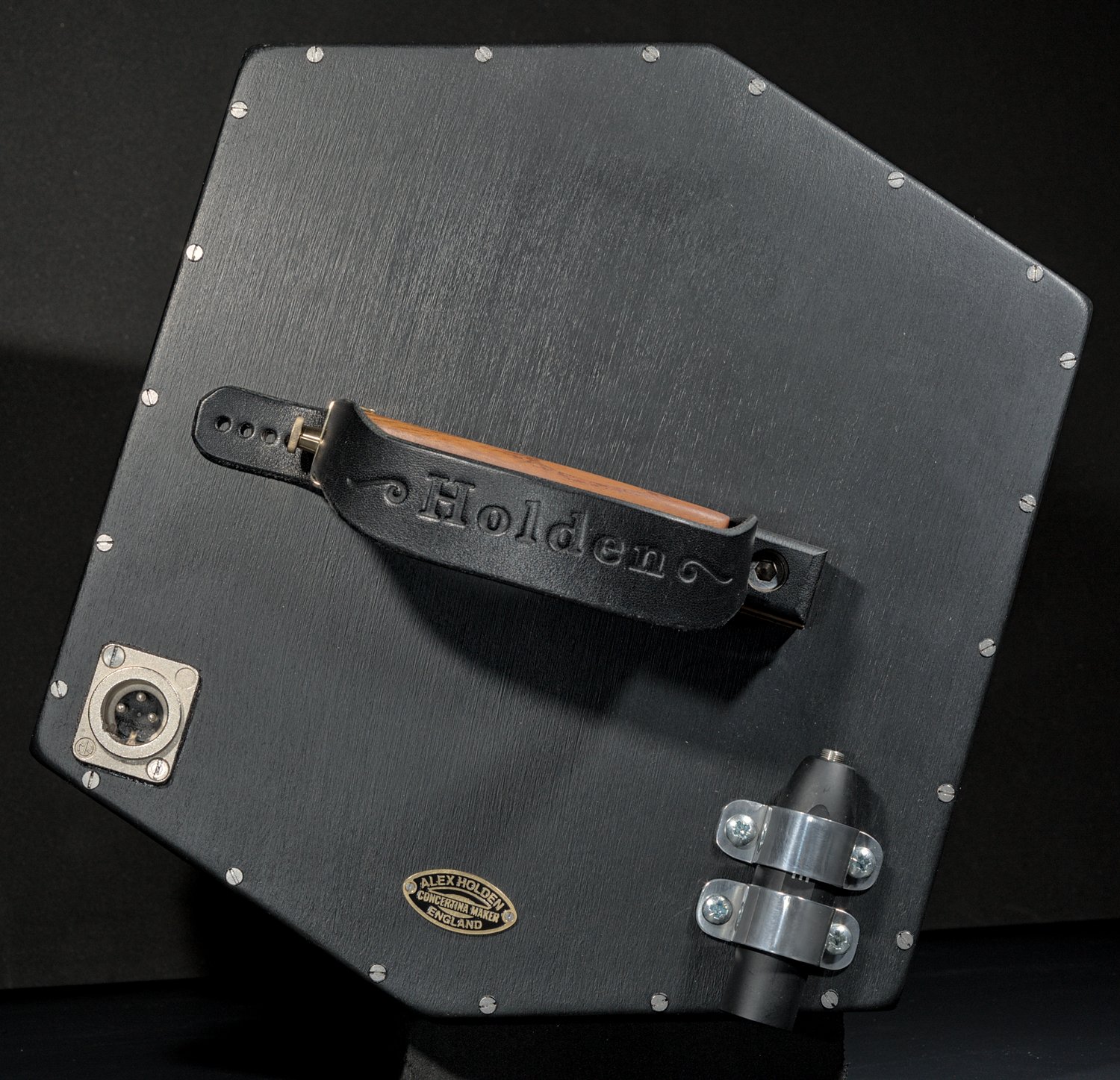
- Internal dynamic microphone with panel-mounted XLR socket.
- External Rode Lavalier Go microphone and VXLR Pro adapter.
- Custom bracket and hinged shelf system for mounting to a bench.
- Foam-lined flight case with tool storage compartment.
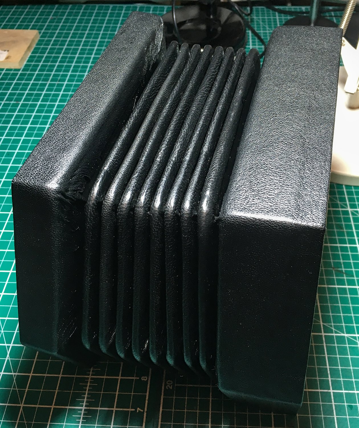
- Reused vintage 8-fold Lachenal bellows.
Exterior
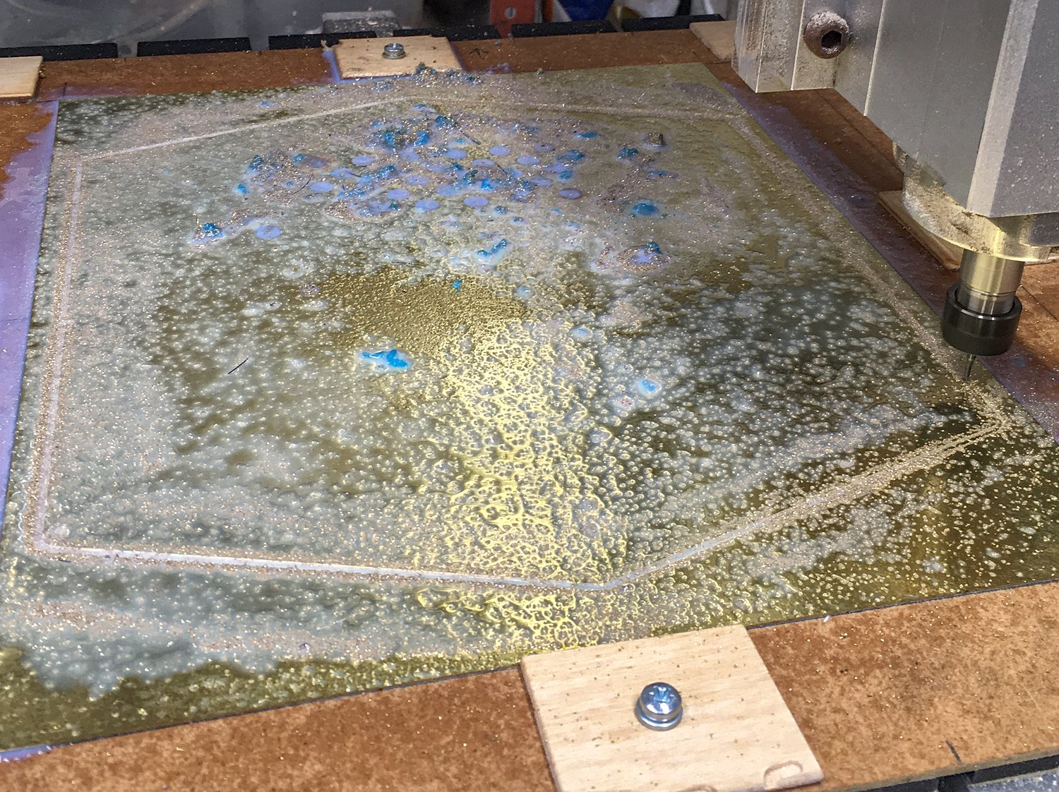
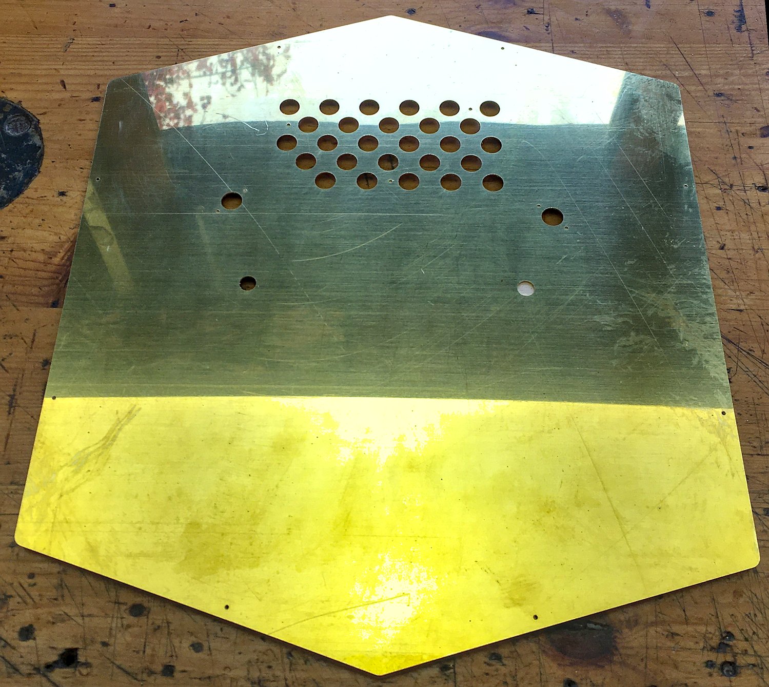
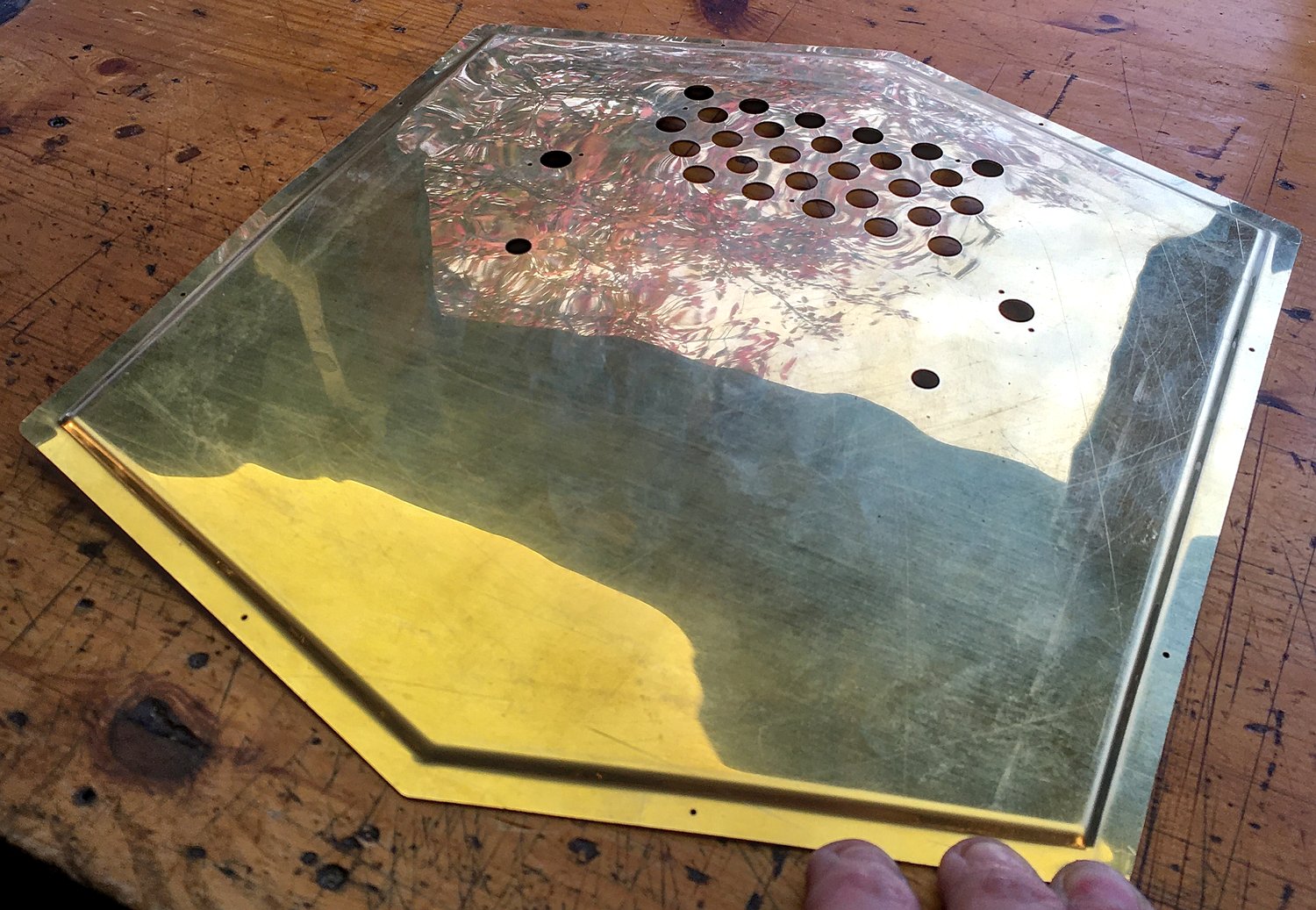
I used my CNC router to mill the perimeter, button holes, end bolt holes, hand rail holes, etc. on the brass end plate. This lets me locate the critical features very accurately, without routing the cosmetic piercings. The machine is rigid enough to cut brass accurately as long as I take light cuts with a sharp tool and use a water-based semi-synthetic cutting fluid, which I applied manually with a brush because the machine doesn’t have a flood coolant setup. The brass sheet was held to a sacrificial MDF board with blue tape and superglue, hence the blue paper gunk mixed in with the coolant and brass chips.
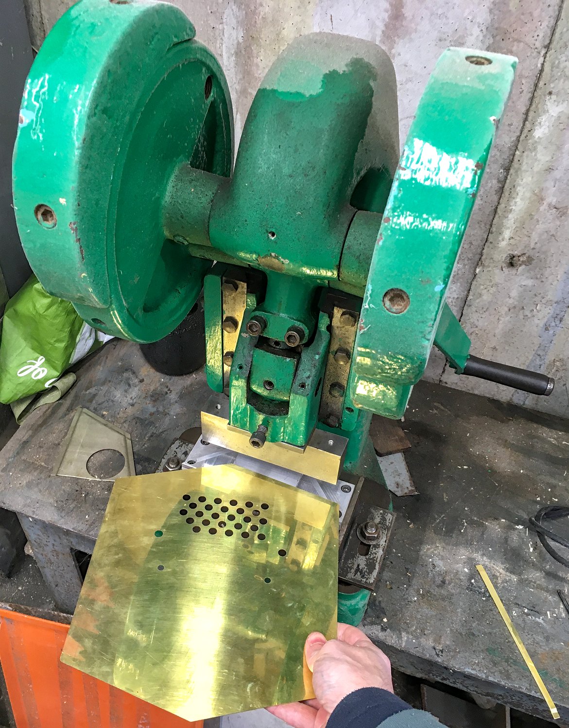
To crimp the edges, I modified my existing press tool slightly so that it only crimps a short section at a time, and I have to manually control where it stops crimping on each edge (using lightly scribed guide lines). This was a bit tricky, especially when I managed to cut my hand by catching it between the press handle and the edge of the brass plate, which annoyingly also made a visible dent on the edge of the plate (the press handle is in exactly the wrong place: in future I want to figure out a way to modify it so the handle is at the top, well away from the workpiece).
I wanted to try making the plate gently dome-shaped without making a wooden mould that would likely only be used once, so I had a go at manually beating it to a pleasing curve by hitting the back of it with a rubber mallet on top of some thick carpet. This isn’t as easy as it sounds because you also need to bend an opposing curve around the outside of the domed area so that the edges are flat.
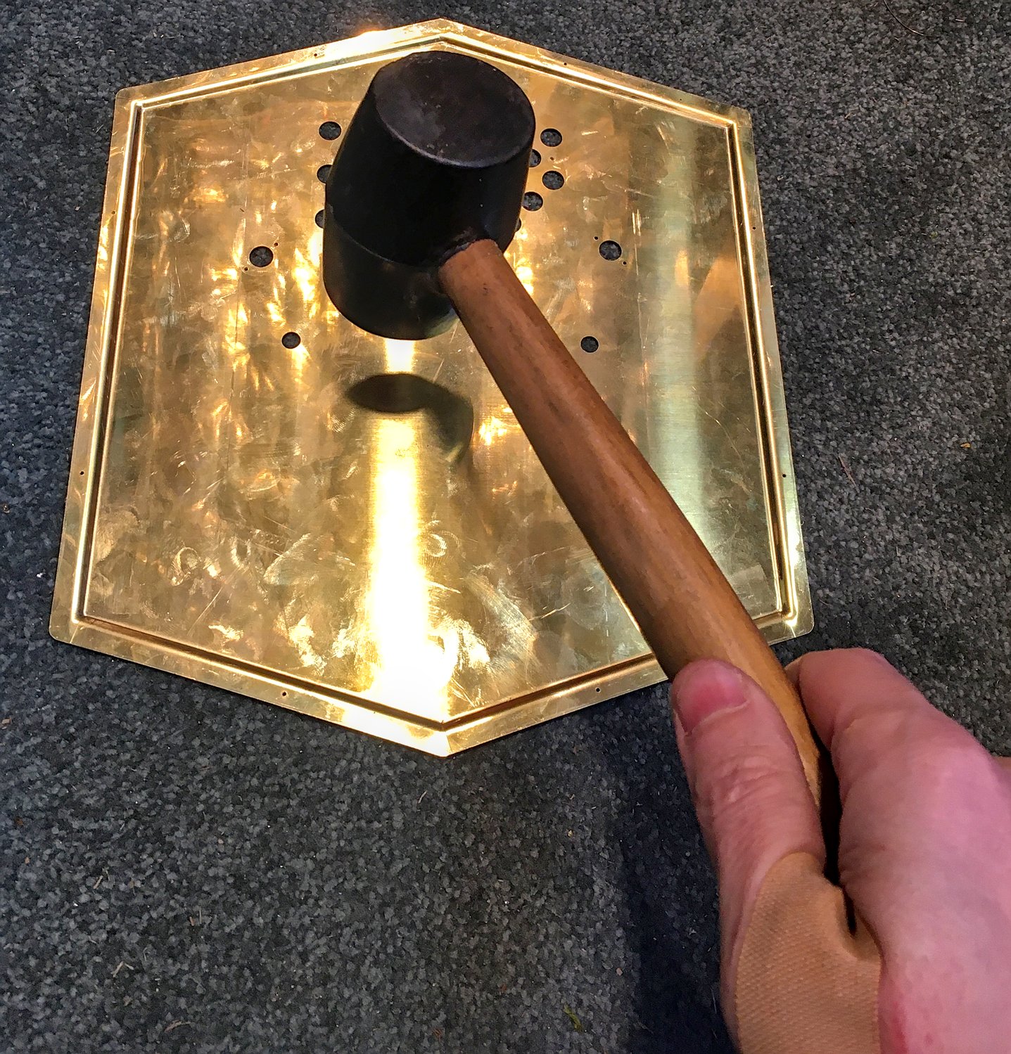
The end result worked out pretty nice. It’s quite a subtle effect but I prefer it to a totally flat end. Because the end is quite large it doesn’t appear to be raised by very much, but there is actually about a 4mm height difference between the border and the centre of the dome (and the crimped border adds about another 3mm). This is more obvious in pictures that show the buttons because the tops of the buttons are all at the same level.
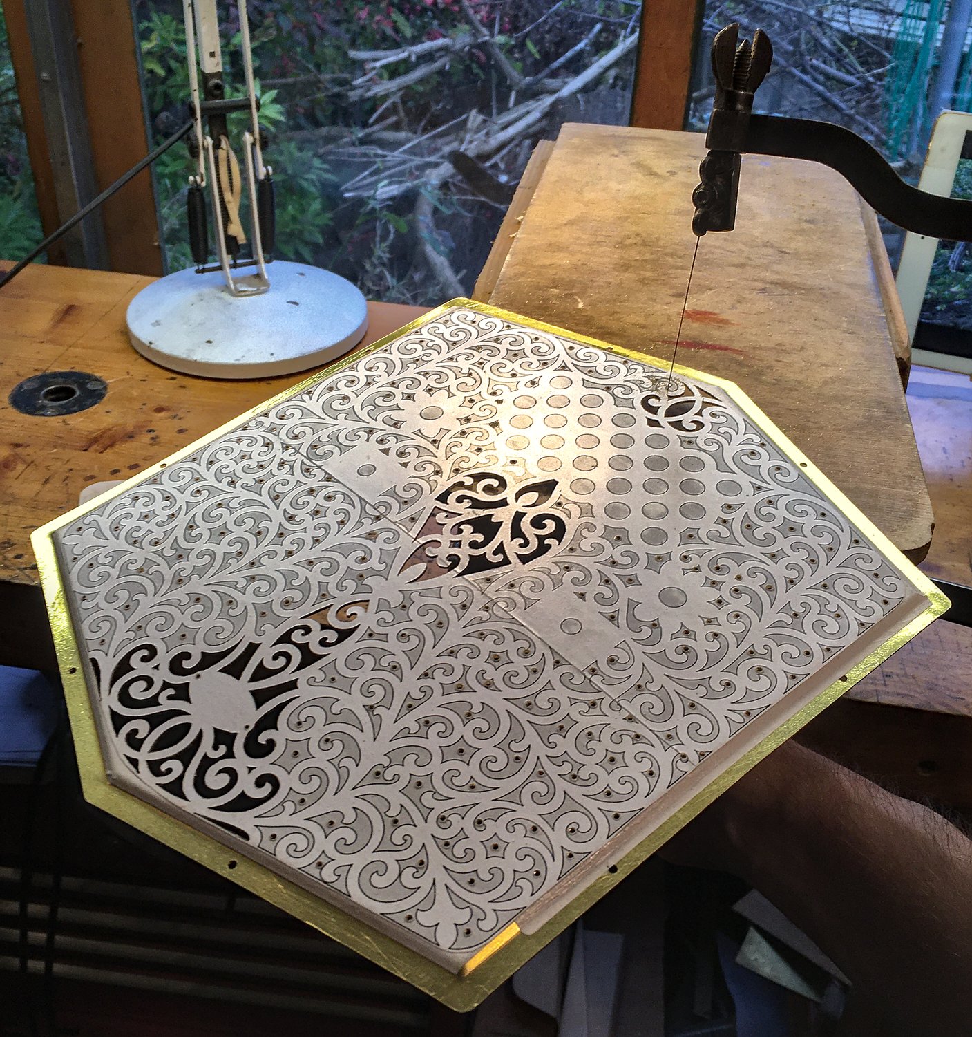
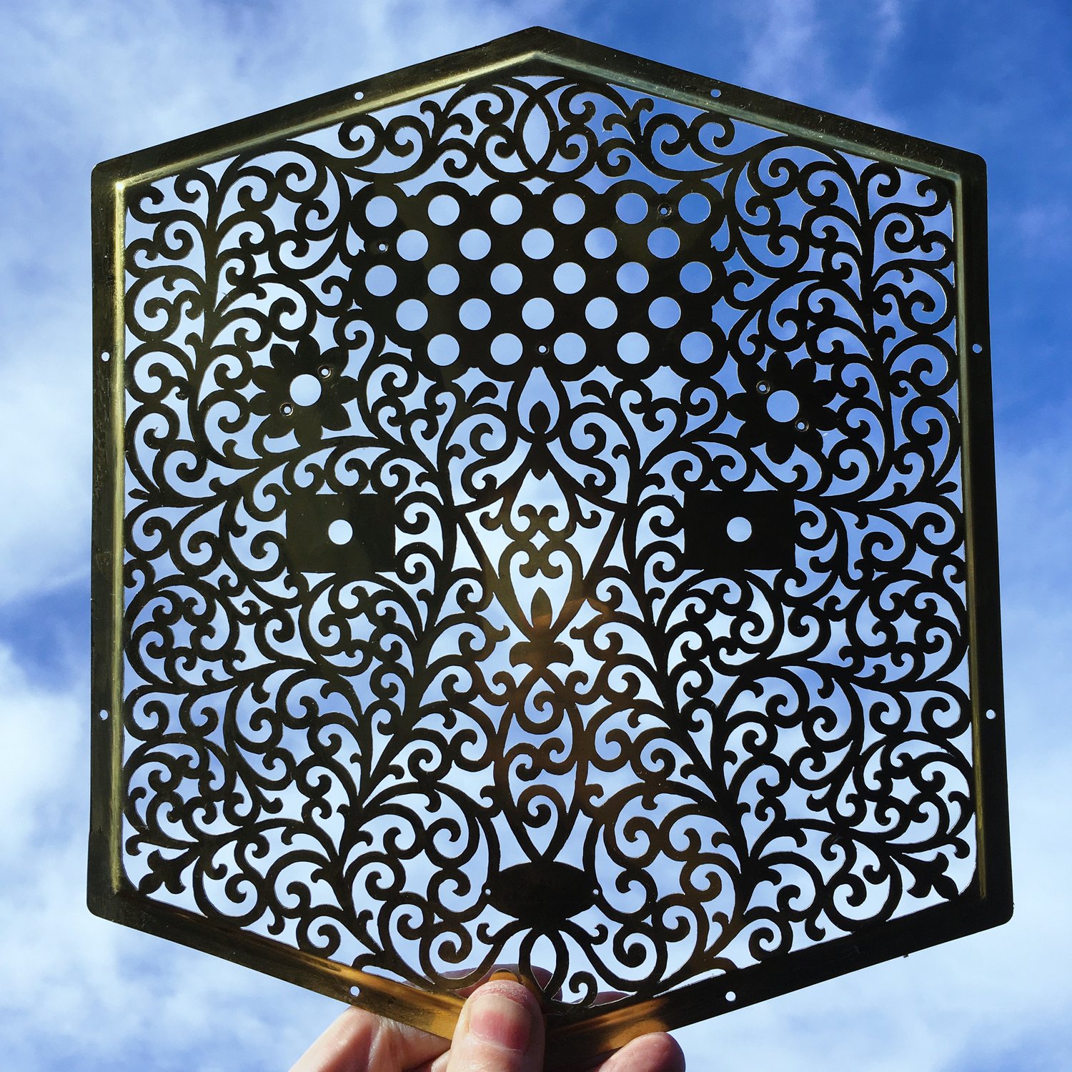
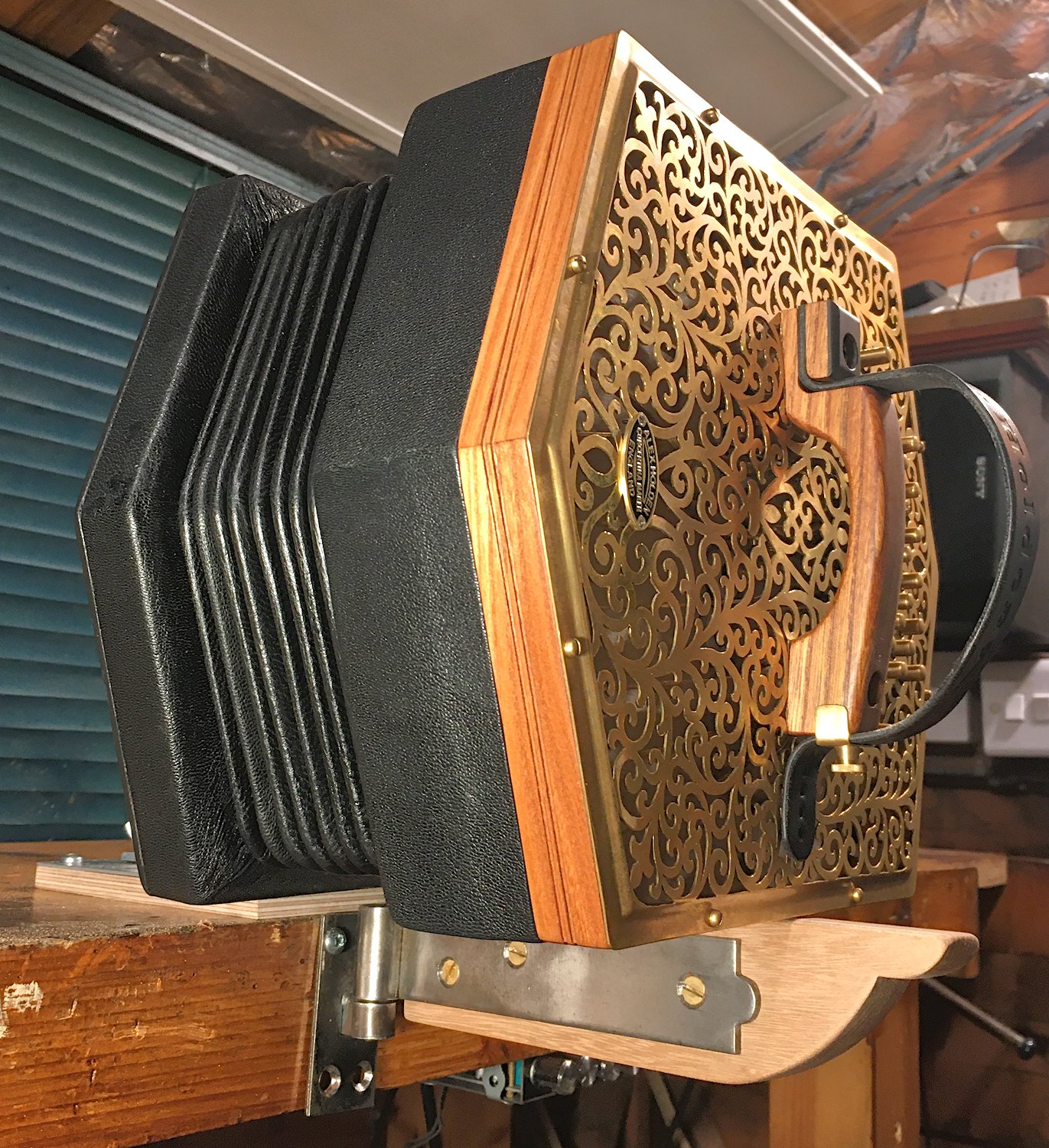
Probably the stand-out cosmetic feature is the fancy hand-cut fretwork, which took quite a while to make. At least I only had to do it on one side!
The button caps and external fittings were also brass, and the action box walls and hand rails were made from solid elm wood with an antique amber Peacock Oil finish.
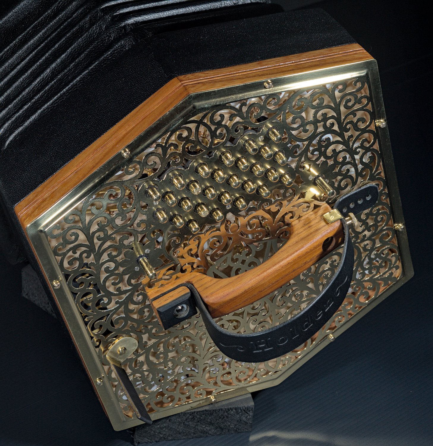
The button bushings were black, and the two C buttons had a texture engraved on the top to make them identifiable by feel (this picture was taken before the final polish). You can see in this one what I mean about the button heights appearing to be taller at the edges of the keyboard than in the middle because the end plate is raised in the middle but the tops of the buttons are level. I have seen the same effect on vintage instruments with similar raised ends.

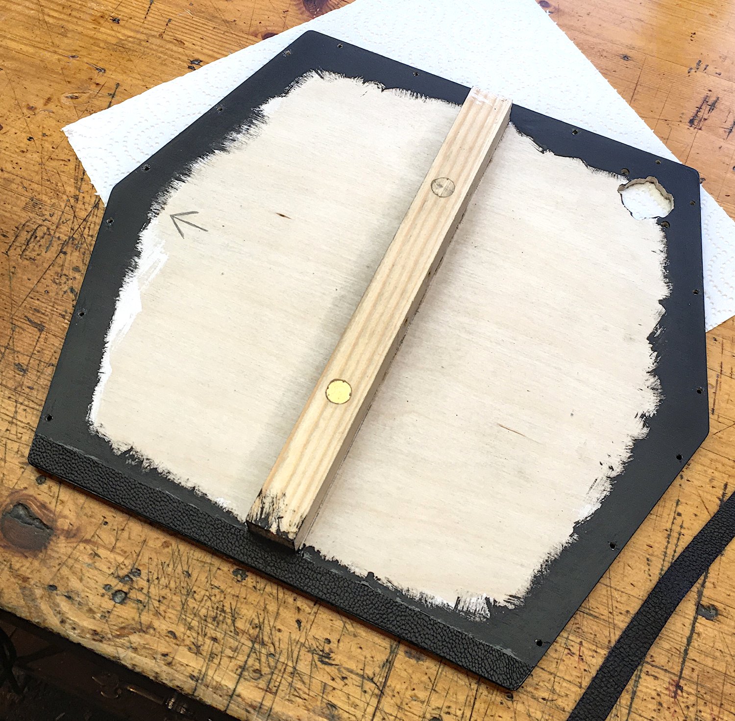
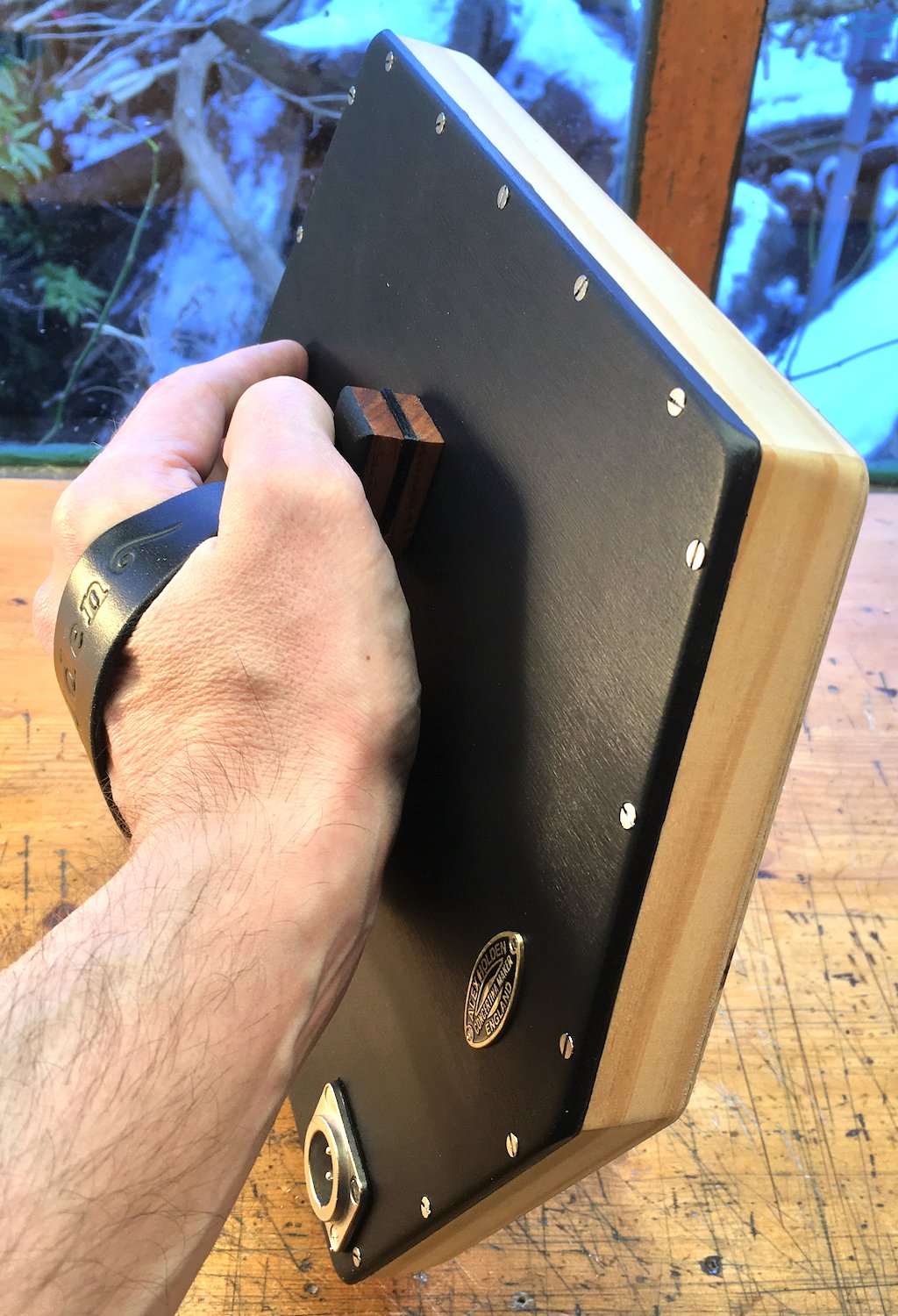
The non-playing end is quite plain: a flat sheet of plywood painted satin black with rounded-over borders, held on with (probably an excessive number of) stainless steel countersunk slotted screws. I chose to make the hand rail in the same style as the playing end, and I added a second maker’s badge.
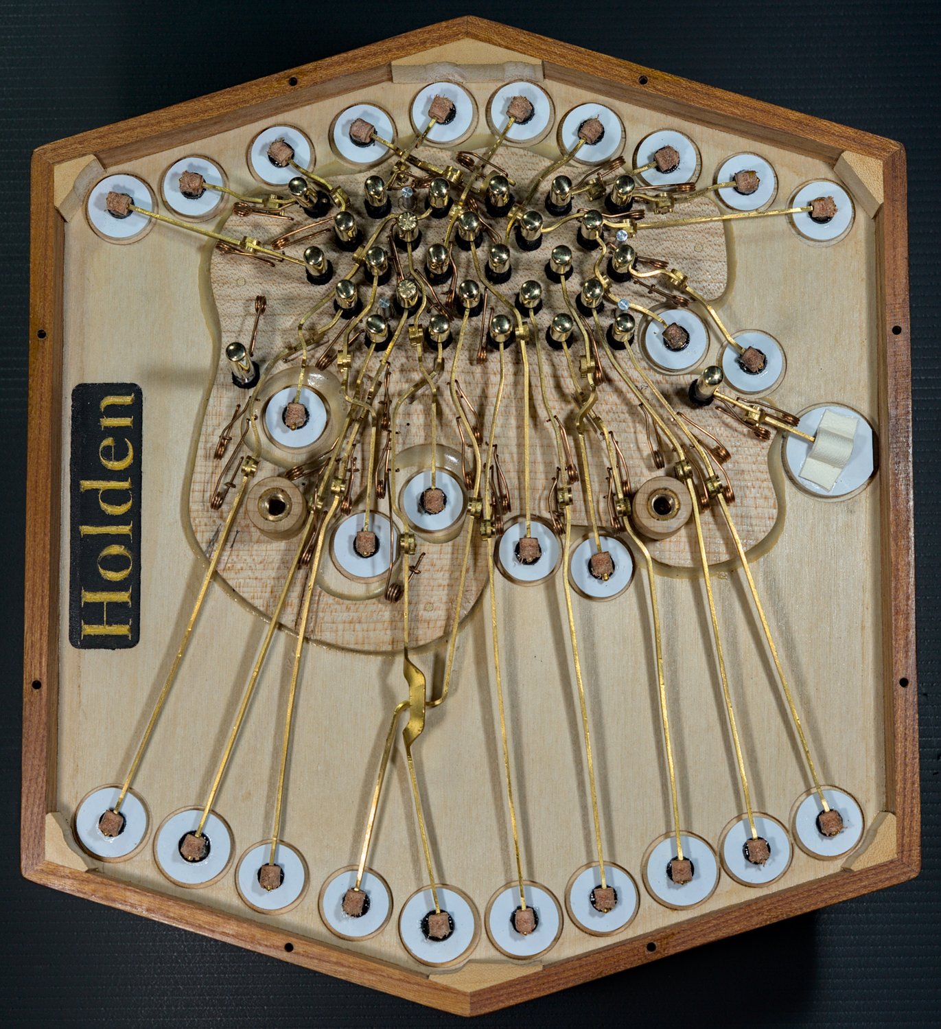
Action
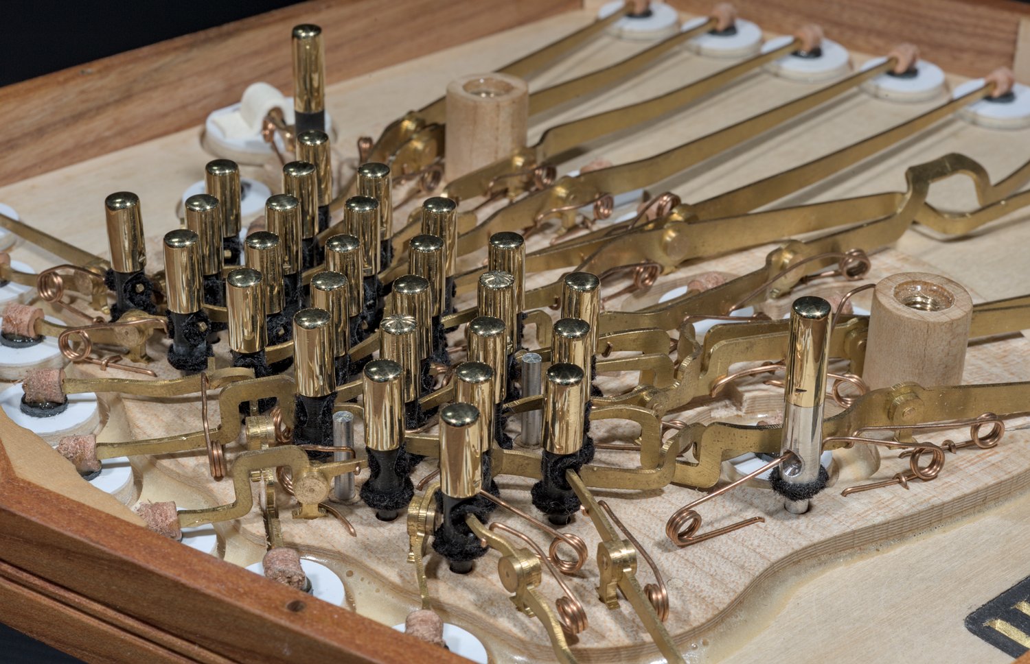
This was one of the most difficult actions I have designed and built, for a number of reasons, particularly the presence of several chambers in the middle of the reed pan (due to my desire to fit as many notes as possible into the available space), and the location of the hand rail support pillars (I put the hand rail in the exact centre of the end, both for balance and cosmetic reasons). I also needed quite a few crossovers because of the reed pan arrangement. I also found that with the extra-long levers going to the pads along the bottom walls of the action box, they worked better if I fitted two springs instead of the usual one, but the extra springs had to fit into the cramped area in the middle of the pan.
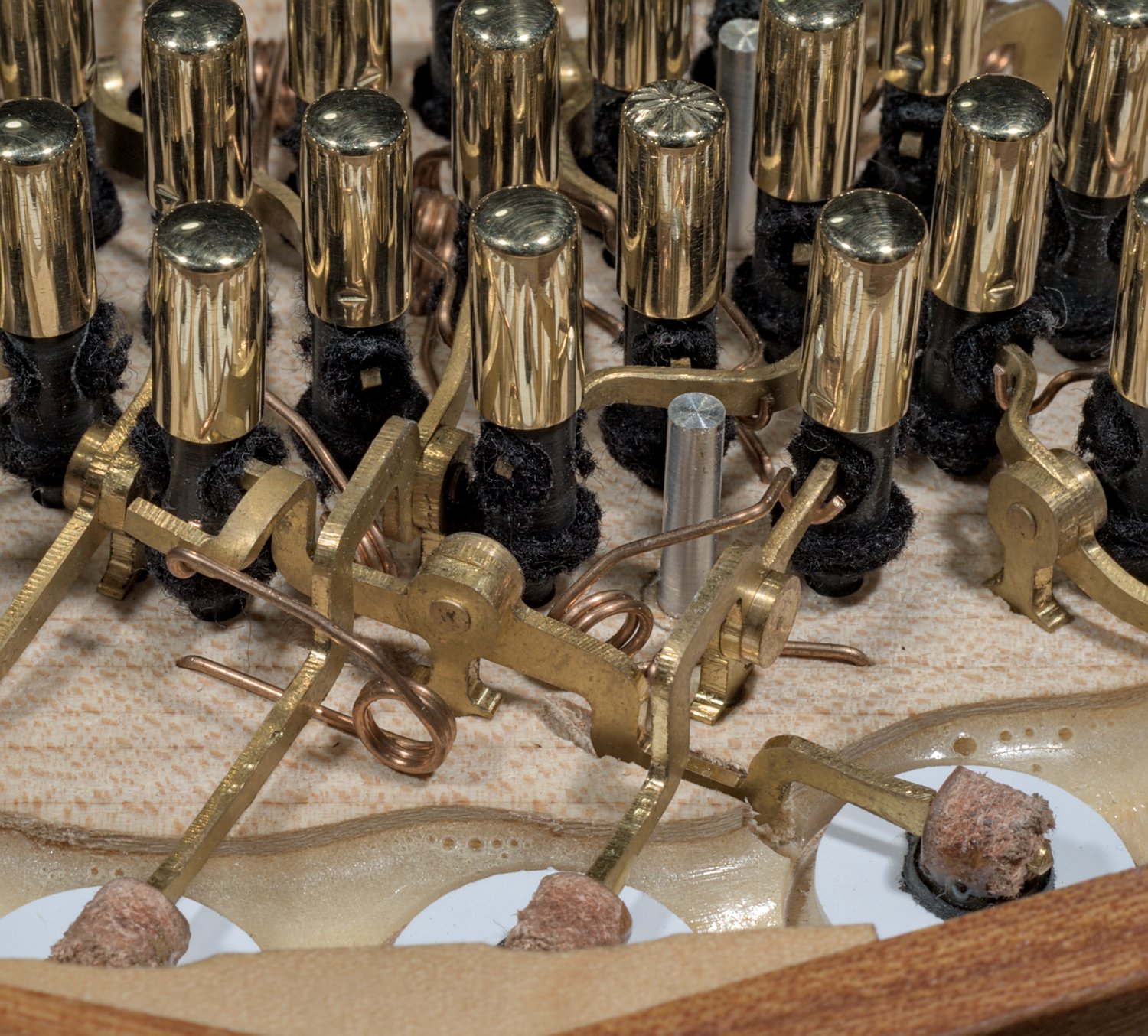
The unusual twisted crossover was a workaround for the fact that, after I assembled it, I discovered that if you hit the button hard enough the ‘over’ lever could tap on the underside of the end plate.

This double crossover was rather awkward. In hindsight I didn’t need to allow so much clearance between the upper and lower levers, but it’s always very hard to judge crossovers at the drawing board.
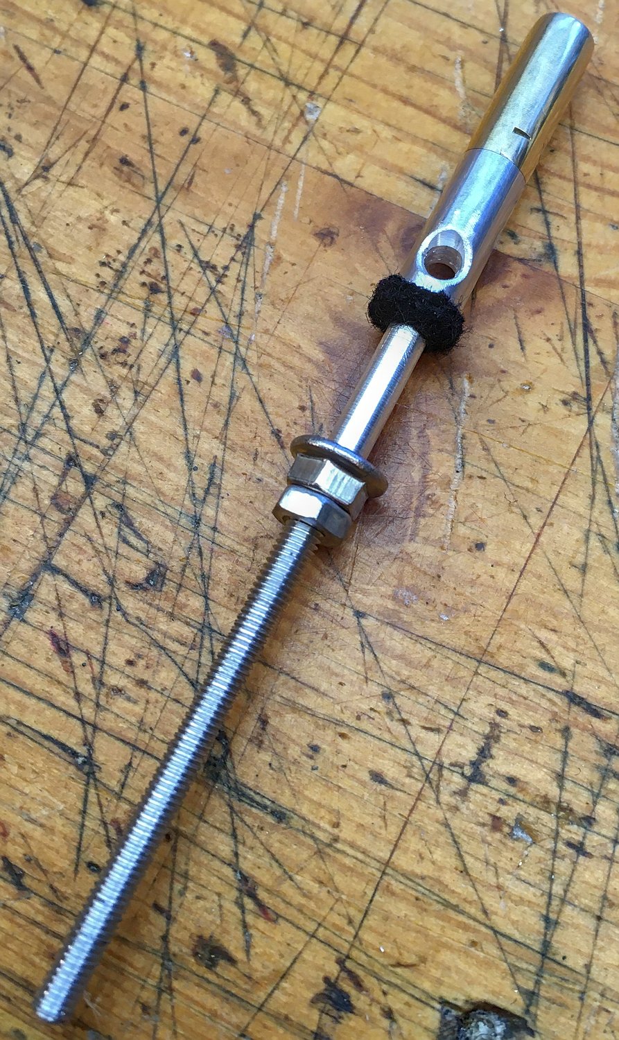
A unique feature of this instrument is the second air button on the left side (where your thumb naturally rests when playing right-handed). The thumb button on the right side of the action box is fairly conventional, albeit significantly longer than the finger buttons. The thumb button on the left side has an aluminium core and appears to have a spring but no lever.
The bottom part of the air button core is actually a long pushrod that goes through the action box, where a flange nut (with an O ring, not shown in the photo) locked by a conventional nut is used to prevent the button rising too far. Below that the threaded rod carries on all the way through a small hole in the reed pan.
Attached to the bottom of the reed pan is a pivot post and a rocker arm.

The other end of the rocker arm pushes on a wooden pushrod glued to the bottom of the air pad.

The idea was inspired by the rocker mechanism in overhead valve internal combustion engines, with the player’s thumb playing the part of the camshaft. The reason I came up with it was because it is possible to configure the concertina to play either left-handed or right-handed, but there was only room for one air port through the reed pan, over on the right hand side. Since the client told me he mostly intends to play the instrument right-handed, that meant that without some clever solution to run a lever all the way across the action box (crossing over about 15 other levers), the air button was going to end up in the wrong place for the right thumb. To his credit he told me he was fine with making it work (you could sort of reach the air button on the right side with your pinky finger), but it seemed inelegant to me. When I came up with the idea of a rocker arm on the bottom of the reed pan it seemed like a bit of a gimmick and I wasn’t sure how well it would work, but actually it works perfectly. While I was tuning and adjusting the instrument I frequently used the right thumb air button and I didn’t once think about the unusual mechanism that made it work.
Reed Pan
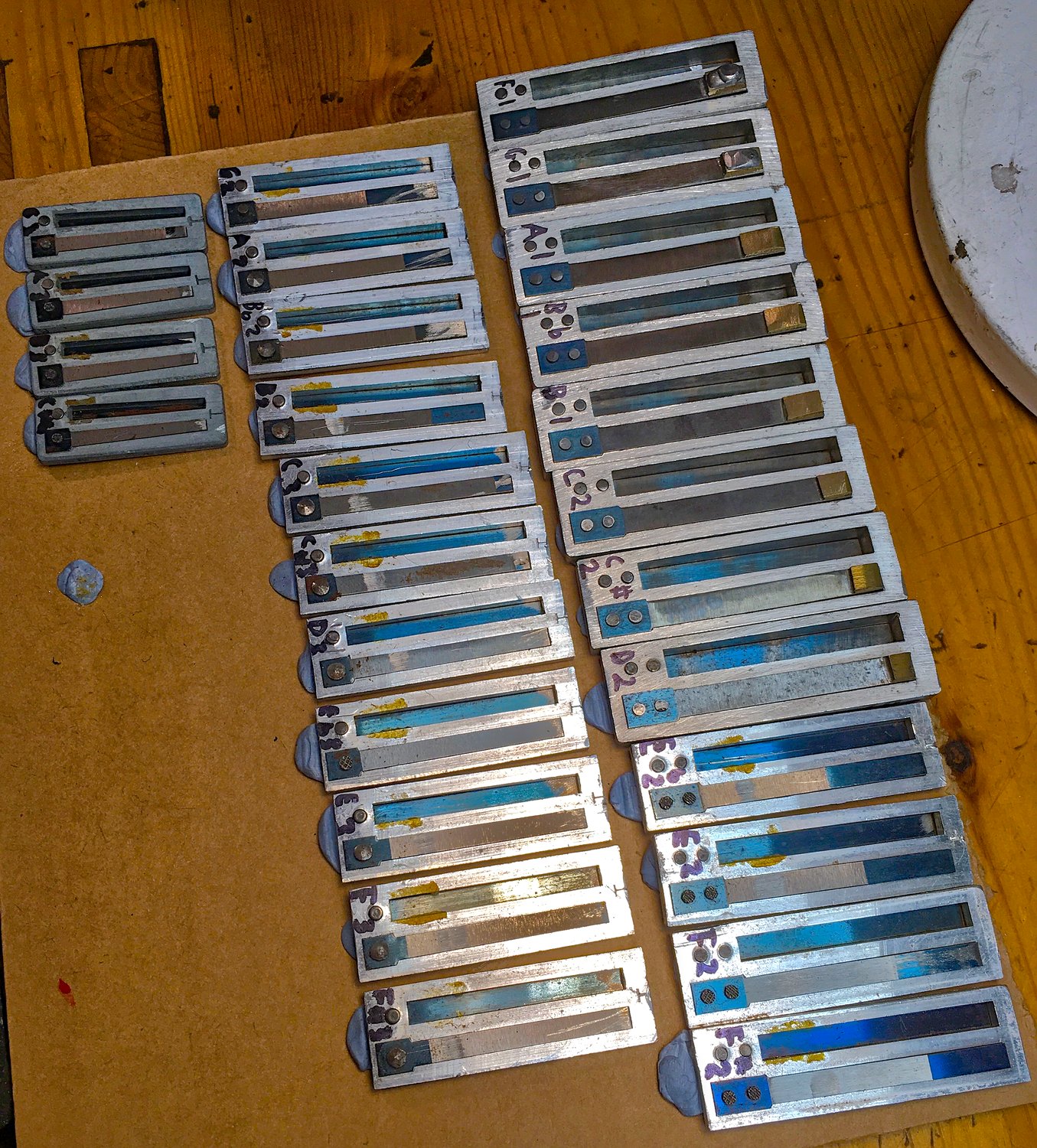
This was the first instrument I have built with factory-made accordion reeds rather than hand-made concertina reeds. The bottom 12 pitches were large new-old-stock Hohner bass reeds bought from a fellow squeezebox restorer. The rest of the reeds were second-hand, salvaged from a set of Hohner accordion bass reed blocks I bought on eBay. The lowest reeds I had available were G#1, so I made the F1 and G1 by adding extra solder to the existing brass tip weights. There were four different sizes and thicknesses of reed plate. They were all aluminium (or maybe duralumin? I’m not sure) apart from the top four pitches, which appeared to be zinc. (Picture taken before I had cleaned them.)
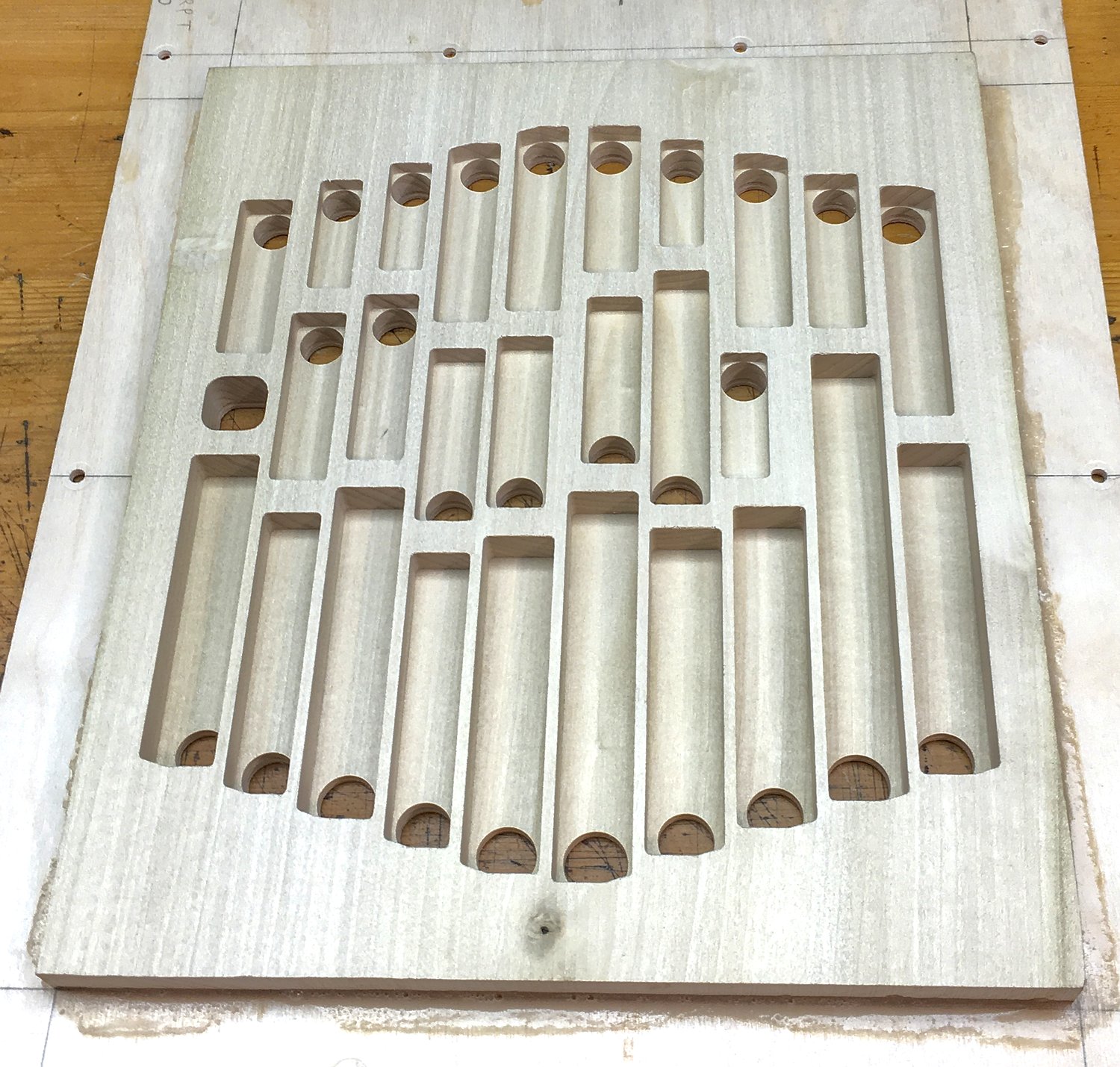
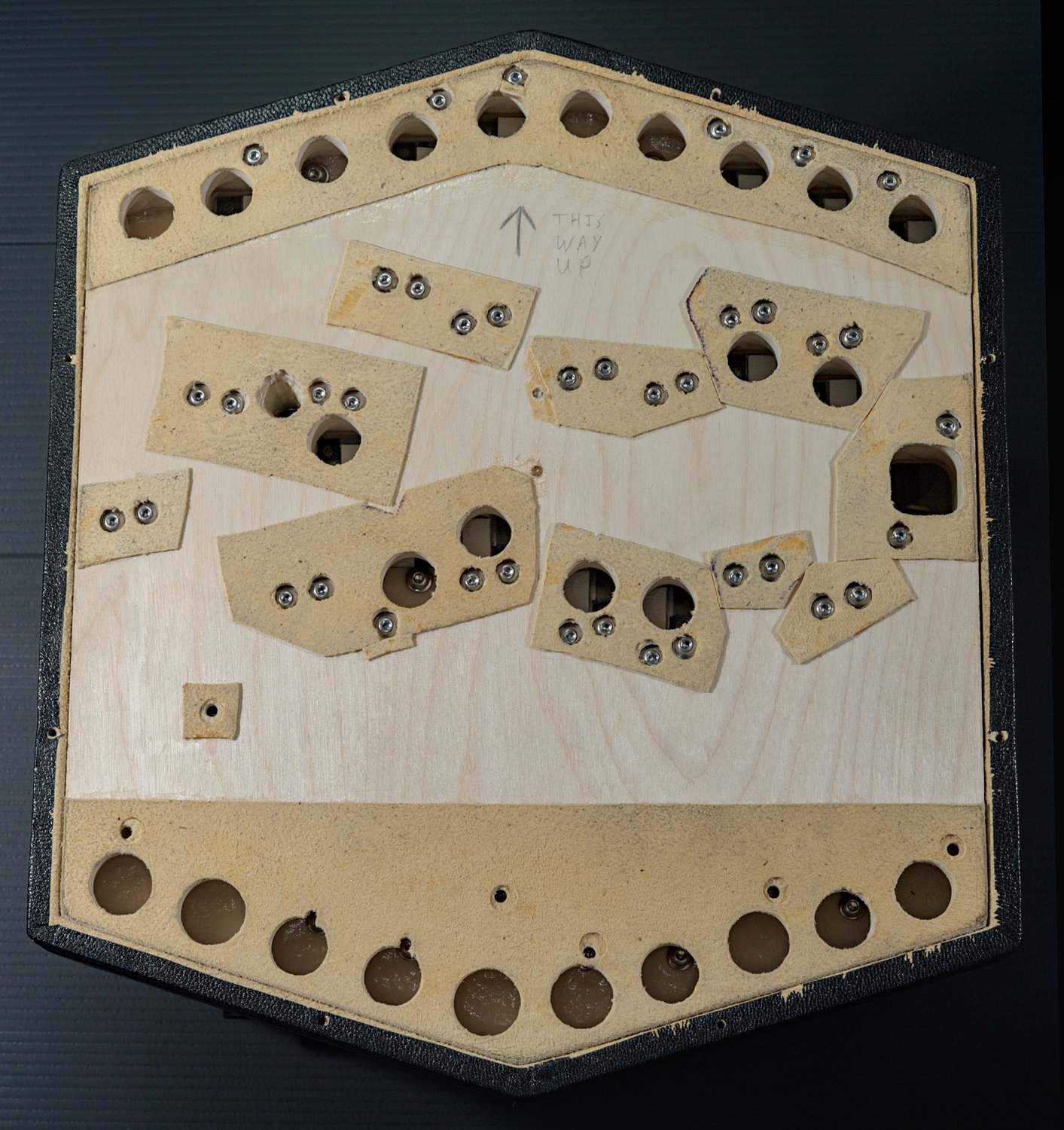
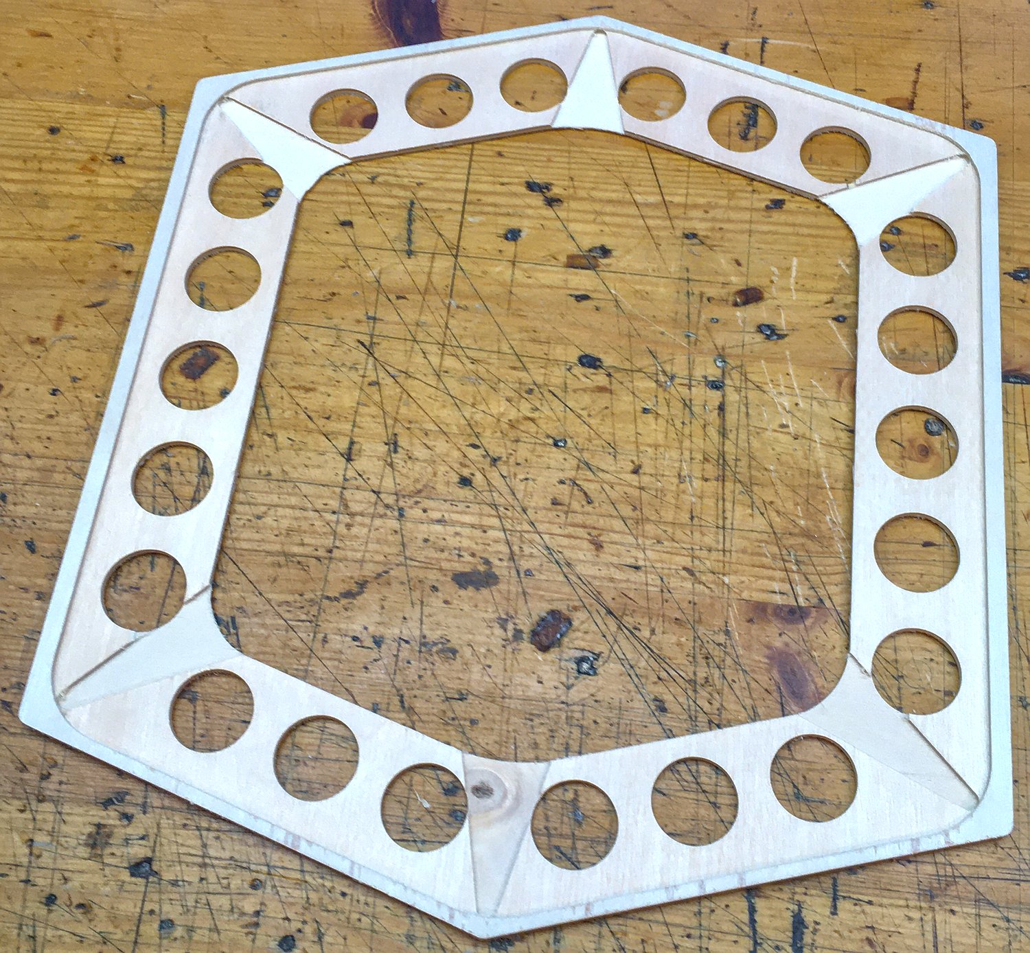
I didn’t want to use accordion-style perpendicular reed blocks, so I arranged the reed plates on a flat reed pan. The design of the pan took some inspiration from other hybrid concertinas I have seen, with a few differences. In particular, many of the bass reed chambers needed to be longer than the reed plate to perform adequately, which complicated the construction somewhat. I decided to make a separate pan rather than integrating it with the bottom of the action box for ease of construction and maintenance. It was constructed sandwich-style, with 3mm birch ply on the top and bottom and 13.5mm of American poplar in the middle, laminated together with epoxy resin.
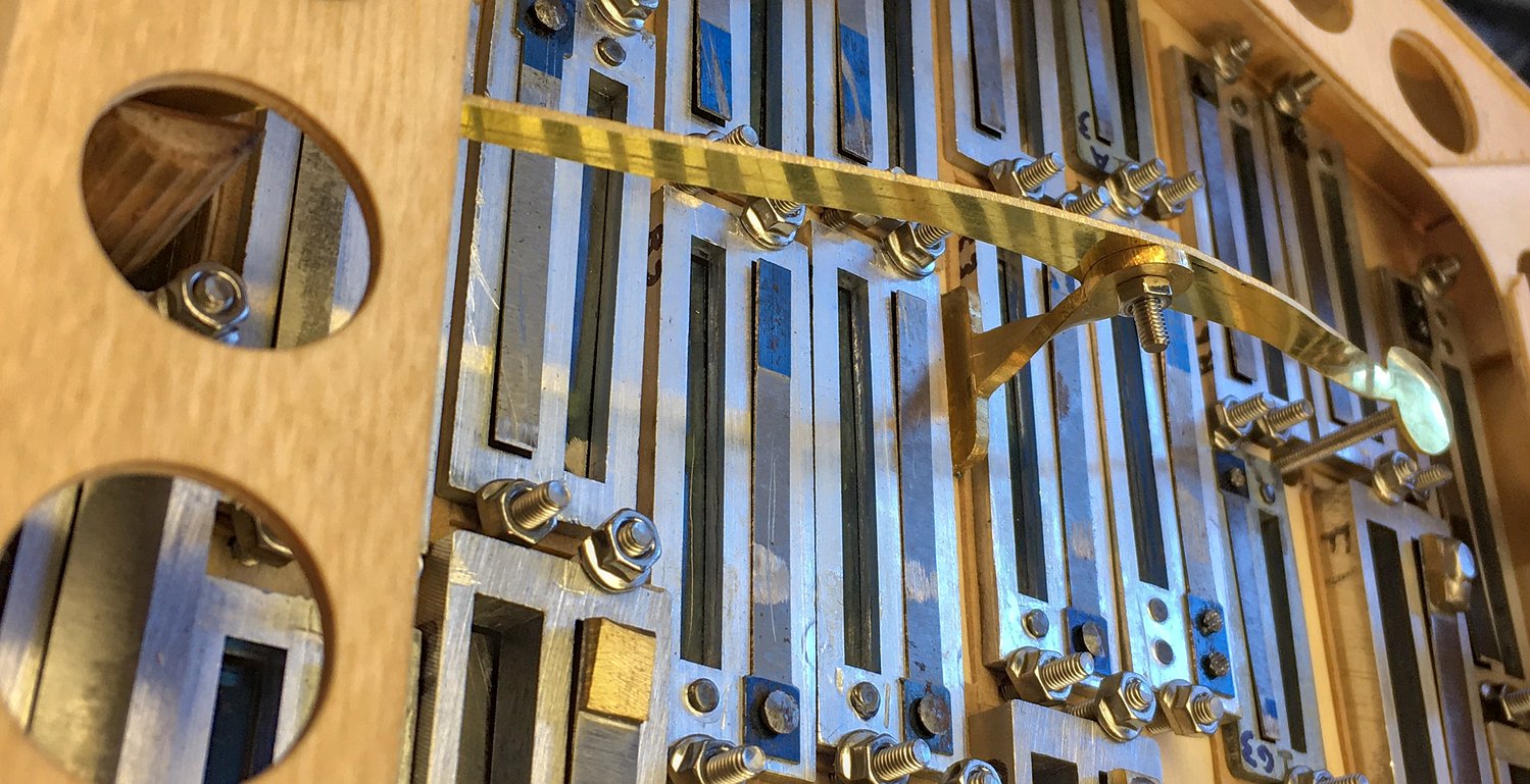
This shows the interior of the pan, before gluing on the bottom layer of plywood:
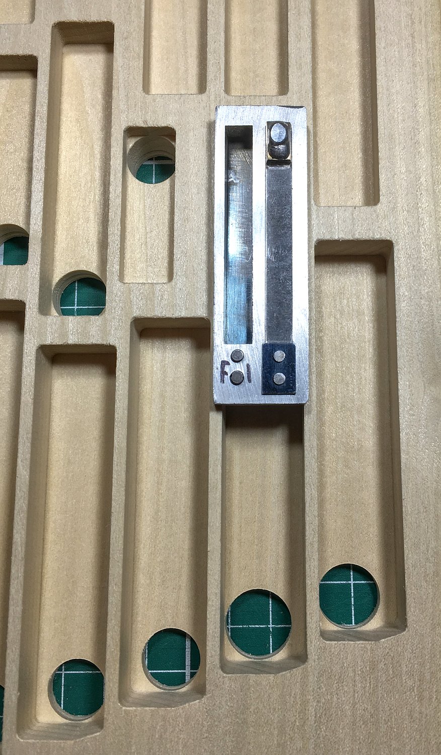
With the F1 reed plate in position over its chamber, you can see how much it was extended (the lower the pitch, the greater the chamber extension). You can also see that I routed the chambers to different depths for each reed plate size because higher pitched reeds benefit from less chamber volume.
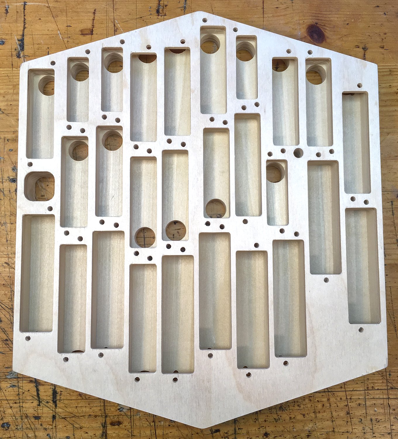
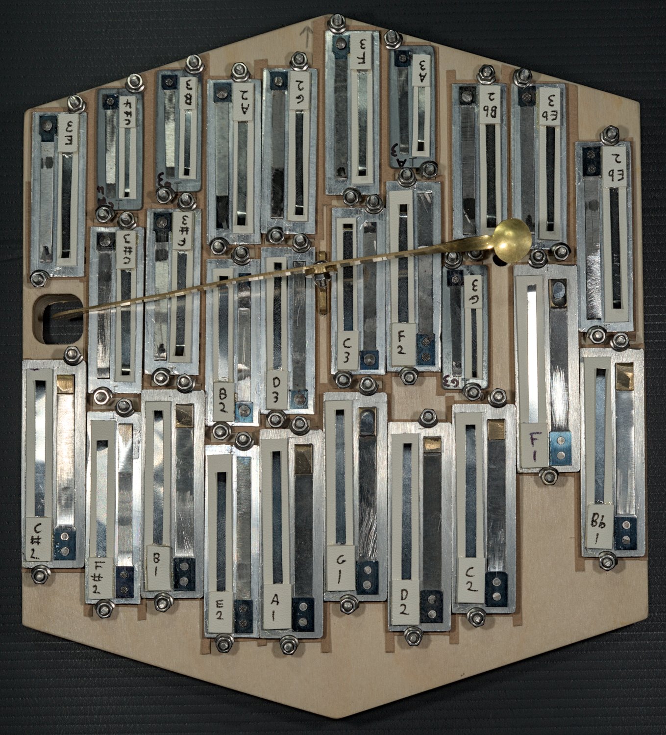
After adding the bottom layer of the pan, the chamber extensions are hidden:
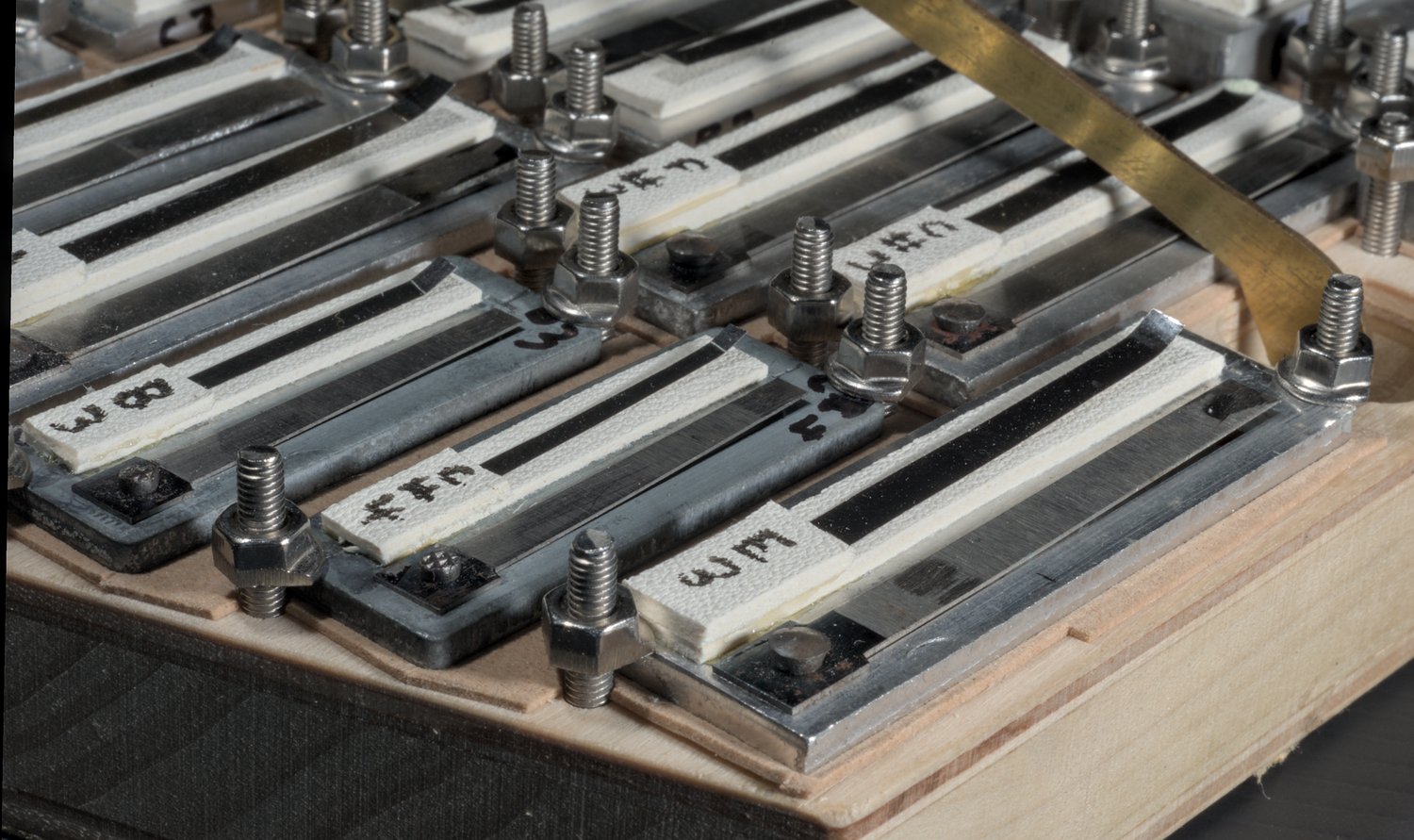
The reed plates were sealed to the face of the reed pan using strips of a thin spongy self-adhesive gasket material called Olovisc.

Each reed plate was screwed to the reed pan using a pair of M3 stainless steel hex button-head screws with serrated flange nuts that I had modified slightly by grinding off part of the flange. There was also a Belleville spring washer under the head of each screw.

This solution may be a little over-engineered compared to the usual self-tapping wood screws, but it does hold the plates very securely and there’s no risk of the thread stripping out of the wood.
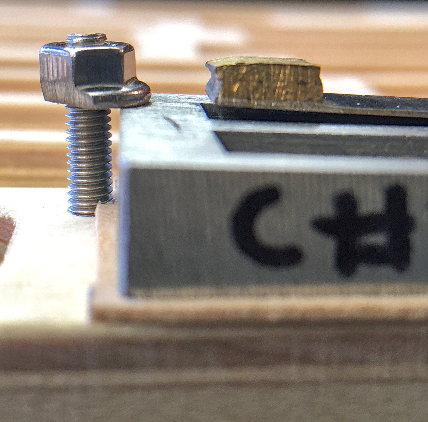
The modified nuts were necessary in some places because I placed the frames so close together.

The heads of the screws were all accessible from the top side of the reed pan. It was sealed to the action box with chamois leather gaskets.
The valves were made from the same sort of sheepskin I use for normal bass concertina valves, with assister springs cut from thin stainless steel shim stock.
I spent quite a while experimenting with different valves and springs on the F1 reeds; it was unusually difficult to prevent them fluttering.
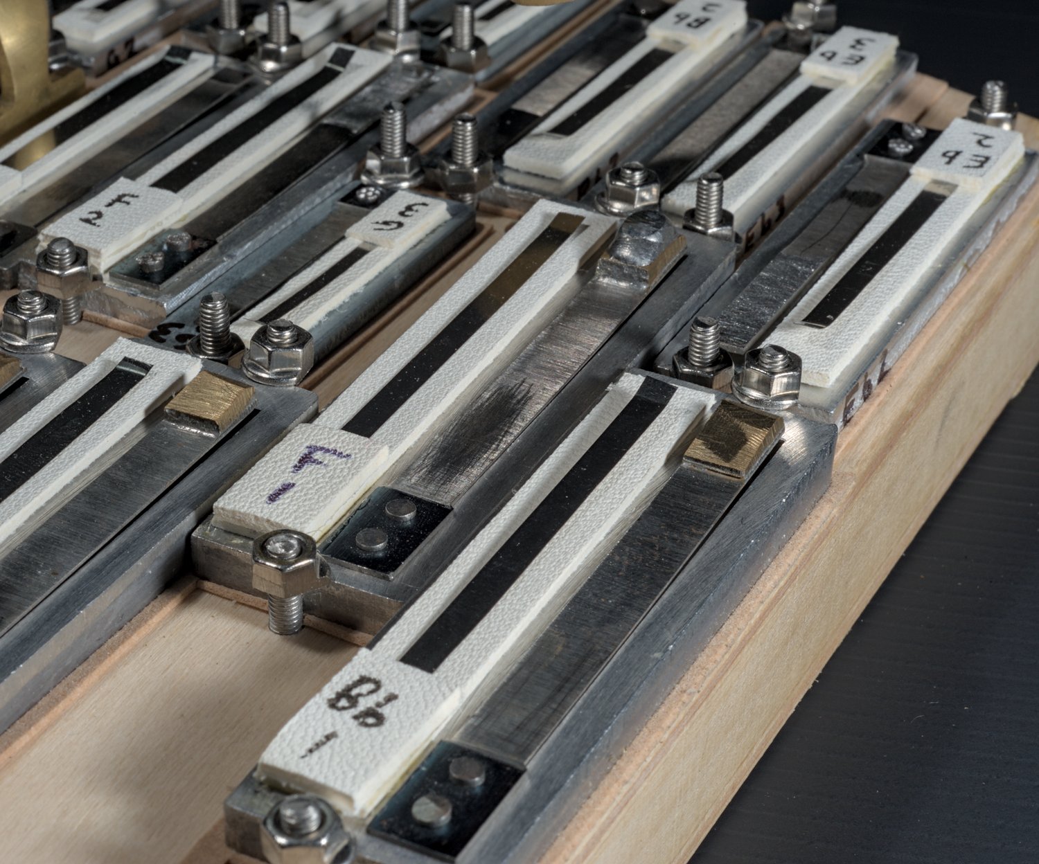
The frames were packed together on the pan pretty tightly. I couldn’t have fitted another note in, at least not without sacrificing the chamber extensions that were necessary to make the lowest reeds perform well.
As far as how the accordion reeds sound, they are certainly different from my own concertina reeds, but I think they still sound pretty good and not too accordion-like. The flat reed pan probably helps with that. One slightly odd thing I noticed is that when playing a scale there is a detectable change in timbre and volume each time it steps up from one reed plate size to the next, particularly between the first and second octave. I don’t tend to get that effect with my own reeds because I make a different frame size for every pitch. I’m probably going to stick to making my own reeds in the future, but I don’t regret the experience of working with accordion reeds and everything I learned in the process.
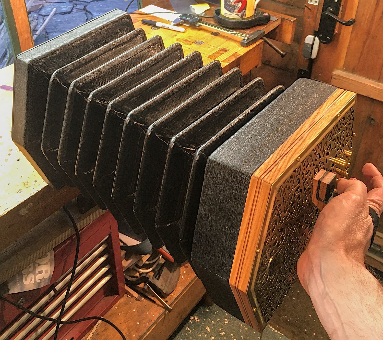
Bellows
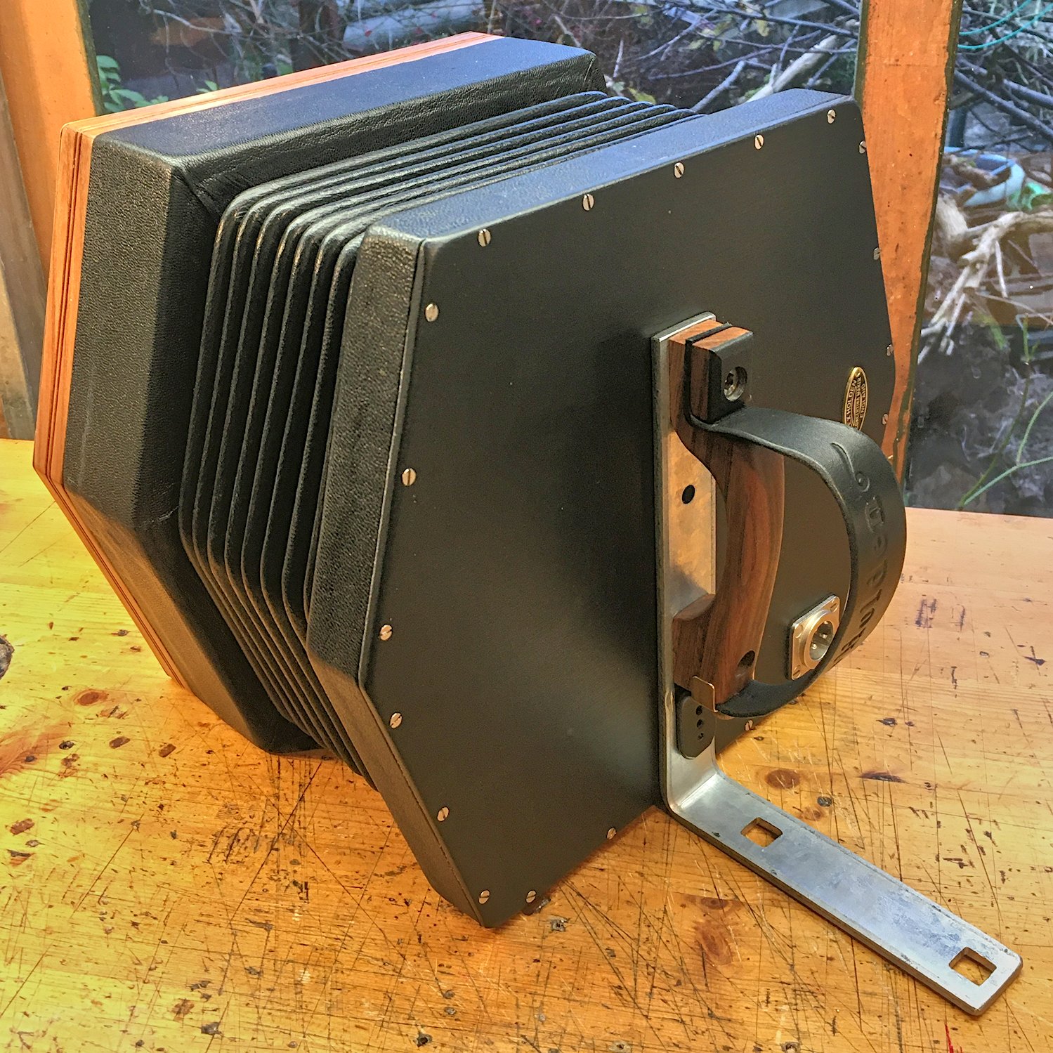
The bellows were salvaged from another concertina: a Lachenal baritone Maccann duet. They were quite old but still airtight. The main problem with them was that somebody had previously rebound them (glued new strips of leather over the top runs), which caused them to be quite stiff despite having eight folds. Nevertheless they were available and about the right size, so I built new frames to fit them and that determined the size and shape of the instrument.
The bellows frames were constructed a little differently from the traditional style I normally use, in that the sides were glued to a 4mm plywood board that both reinforced the structure and had a rebate for the bellows cards to sit in. I have seen other hybrid concertinas that have a similar construction.
The sides were made from reclaimed spruce boards. The thickness wasn’t tapered like a traditional bellows frame.
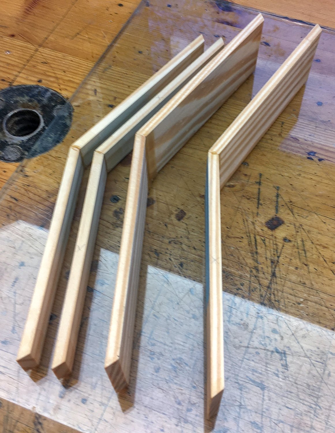
I only fitted one spline to each corner joint because the reed pan was a loose fit and the plywood also helped to strengthen the corners.

The frames with the reed pan in them needed to be unusually deep, but the blank end could be much shallower.
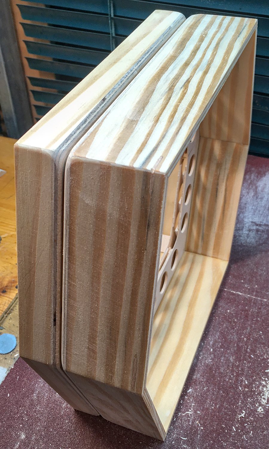
The bellows side of the plywood had rebates cut into it for the cards and the gusset folds. The other benefit of the plywood is that it ensures the folds can’t push into the space inside the frames and potentially contact the reeds. The holes were just there to lighten them a little bit.

The rebates helped me to align the pre-made bellows to the frames without an assembly jig.
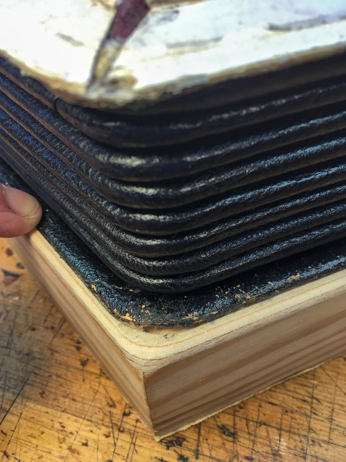
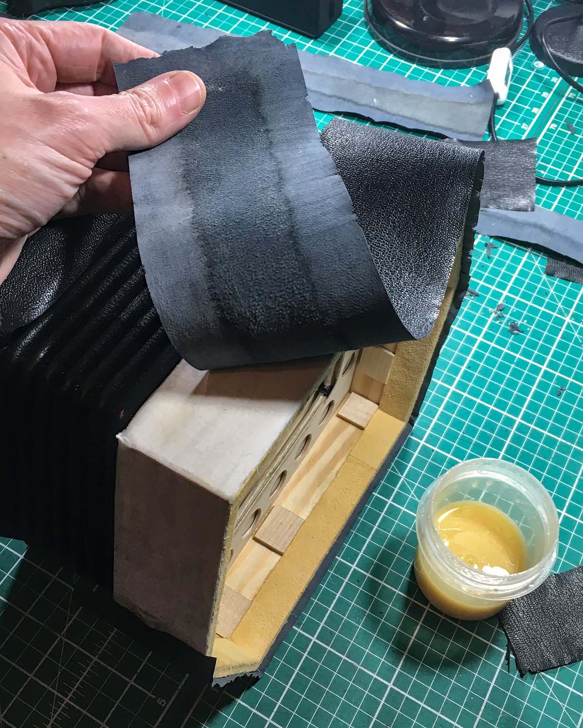
I had to use new linen hinges and leather covering to attach the bellows to the new frames.
Hand Rails
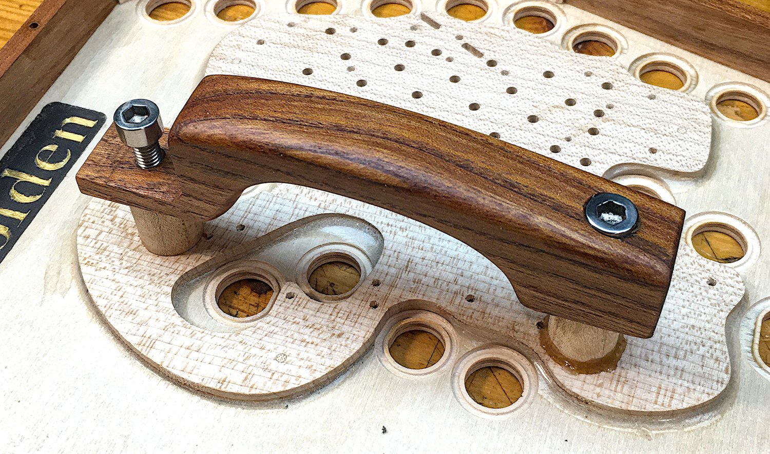
The hand rails were wider than usual and curved for comfort. I made them from solid elm wood and finished them with Peacock Oil like the action boxes. They were arch shaped, partly for cosmetics and partly to expose the fretwork piercings beneath the middle of the hand rail and the four pads beneath them. The one on the action box end had to have curved feet to match the raised shape of the end plate, whereas the one on the blank end had flat feet.
The hand rails were attached using a pair of M6 stainless steel hex bolts screwed into brass captive nuts. This allows for easy reconfiguration, either turning the hand rails 180° to swap between left-handed or right-handed playing, or to attach the blank end to the bench mount bracket (see later).
The captive nuts in the blank end were glued into an internal pine crossbar to spread the load across the end board.
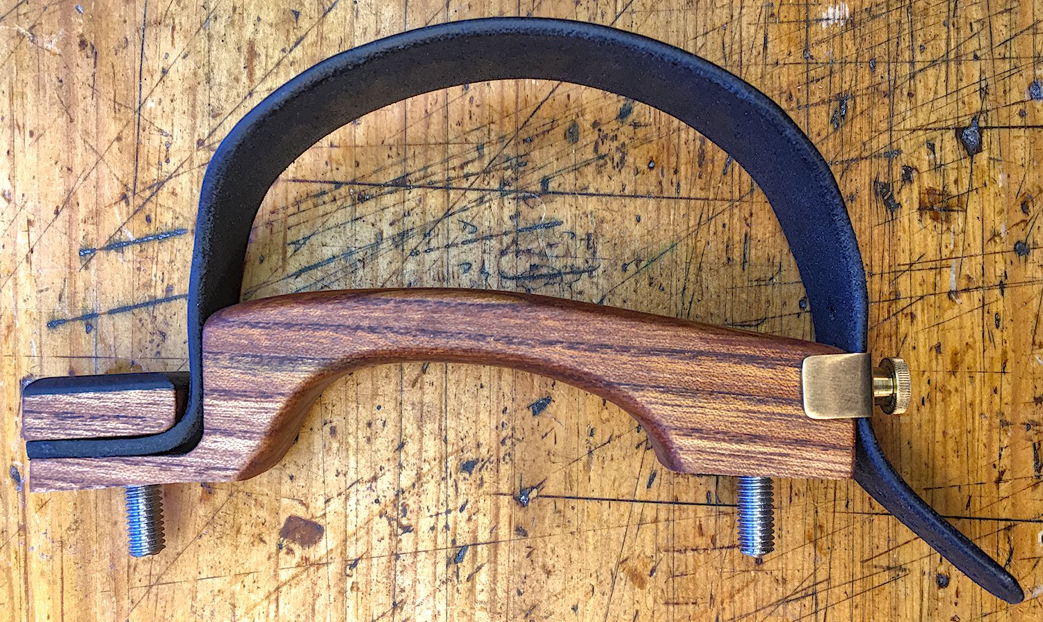
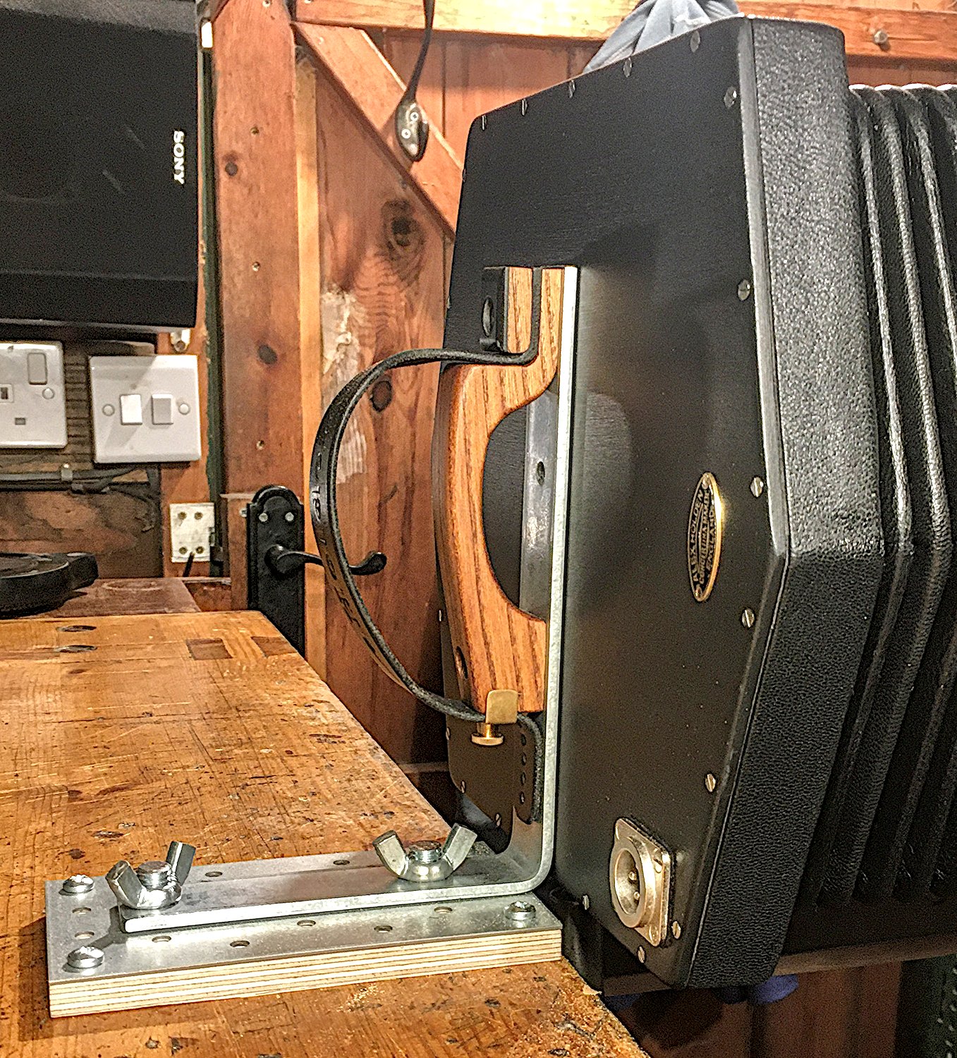
Bench Mount Bracket
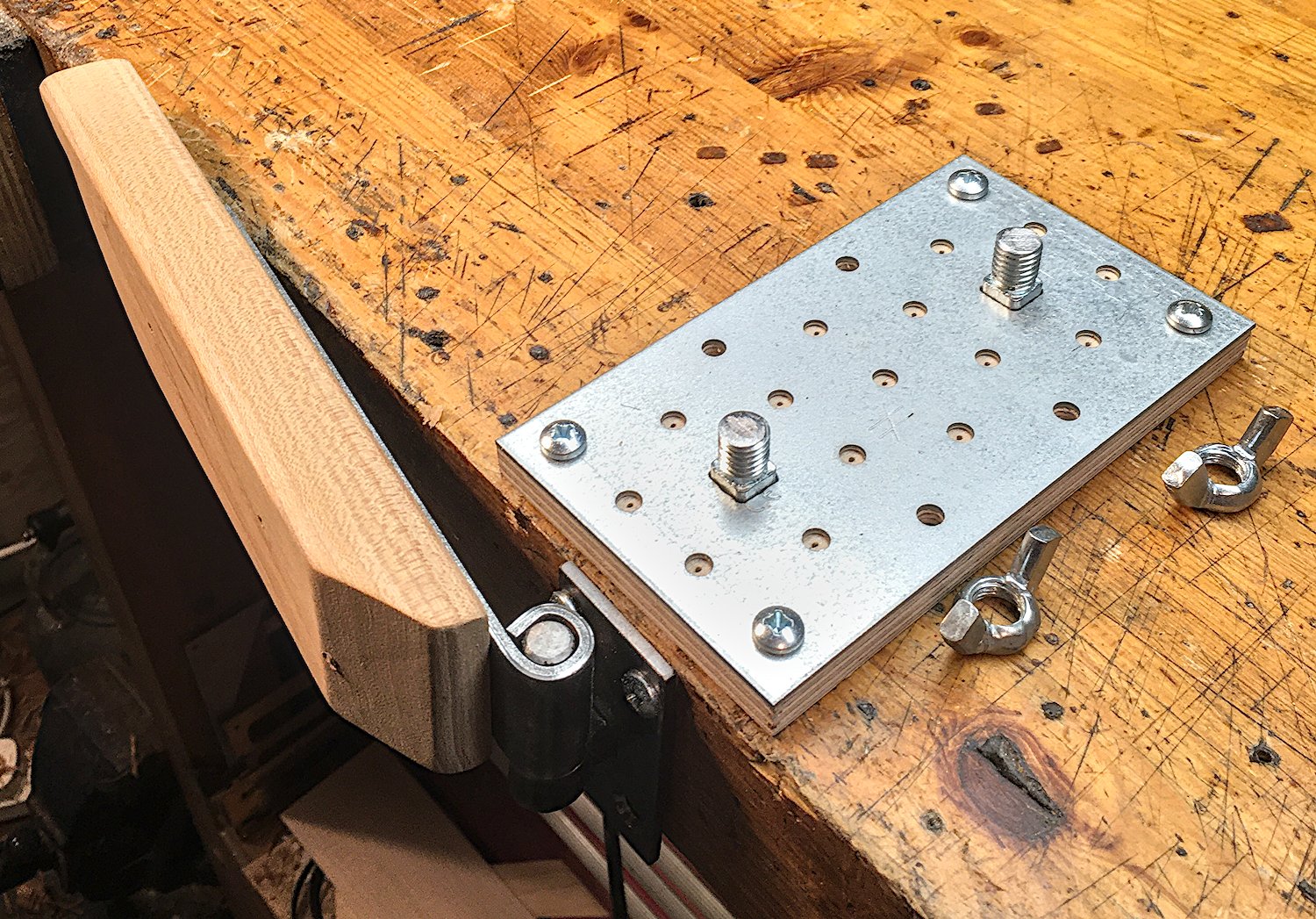
The bench mount bracket was an idea my client had that allows the instrument to be played one-handed with the blank end attached to the end of a bench. This frees the player’s other hand to simultaneously play a different instrument, e.g. a synthesiser. Because the captive nuts are arranged symmetrically it can be assembled either way round, for either right or left-handed playing. It was designed to be disassembled and reassembled quickly so the instrument can be easily transported. The system is made up of several pieces: a steel L bracket that mounts to the blank end of the instrument beneath the handrail, a block with two M6 studs and a pair of wing nuts that screws to the top of the bench and the L bracket bolts onto, a hinge pintle that screws onto the end of the bench, and a hinged wooden support that the action box can be rested on while not actively playing the instrument.
Microphones
My client wanted me to include a built-in microphone pickup both for amplification when playing live, and to feed into a chain of effects pedals. I thought this would be a simple task but it actually proved to be the hardest part of the project. My first thought was that I could mount the mic inside the instrument. It would need to be securely attached with a shock-absorbing mount so that the sensitive capsule didn’t get damaged if the instrument got knocked around a bit. I also thought a dynamic capsule would be a good idea because they are said to be more robust and less prone to feedback than condenser mics, and also they are simpler to hook up to other equipment because they don’t contain any active electronics that need to be powered by phantom power or an internal battery. Because the mic would be inside the instrument, the connection (preferably a standard XLR socket) would need to be on the outside without introducing an air leak in the process.
First attempt: I bought a very cheap dynamic mic capsule on eBay. It didn’t work. I threw it away.
Second attempt: I dismantled a cheapish karaoke-style dynamic mic to extract the cartridge from it, and made a shock mount to attach it to the cross bar on the inside of the blank end plate.
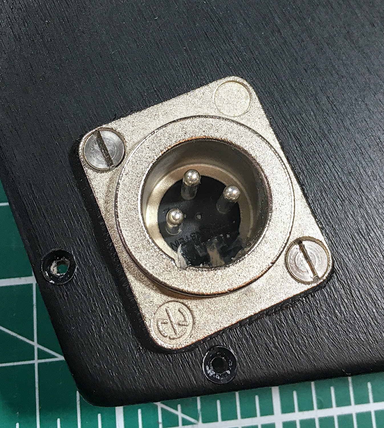
I also fitted a panel mount XLR socket, sealing it with a leather gasket and liberal amounts of silicone sealant.
The internal dynamic cartridge worked, however it sounded pretty bad. It could pick up the sound of the reeds playing but they were very distorted and nothing like the clean sound you hear with your ears. I initially attributed this to the fact that it was only a cheap mic.
Third attempt: I bought a second hand decent-quality dynamic mic on eBay. It arrived very badly packed and didn’t work. The seller was a massive pain to deal with. I eventually got a refund from eBay.
Fourth attempt: I changed tack and decided to try a slightly more expensive new lavalier mic with a phantom power XLR adapter. It was a little tricky to find one that claimed to have a bass frequency response lower than the lowest note in the instrument. Feeling very wary of buying second hand audio gear on eBay after my previous experience, I instead bought them from a big online audio equipment supplier with a fairly good reputation that you have probably heard of. It arrived very badly packed and didn’t work. The supplier was a massive pain to deal with, not helped by the fact that they are based in a different country and we were in the run-up to Christmas by this point. I eventually got a refund for the mic but not for the postage and no apology for wasting my time and not believing me when I told them it didn’t work.
Fifth attempt: I bought a different brand of mic and phantom power XLR adapter (a Rode Lavalier Go and a Rode VXLR Pro) from a UK-based camera dealer. I was getting a bit paranoid at this point and half-expected it to arrive badly-packed and broken, but it was fine and in initial testing outside the instrument the recordings sounded very nice. I then tried mounting it inside the instrument. This was a little fiddly because, to avoid modifying the XLR adapter, I wired in an internal XLR plug. I also made a shock mount for the mic from stainless steel wire.
Unfortunately it sounded absolutely terrible inside the bellows. It was constantly clipping even at the lowest gain and playing the instrument very quietly. This makes me suspect the sound pressure levels inside the bellows must be far higher than outside, and the dynamic cartridge coped better than the electret condenser when being massively overdriven.
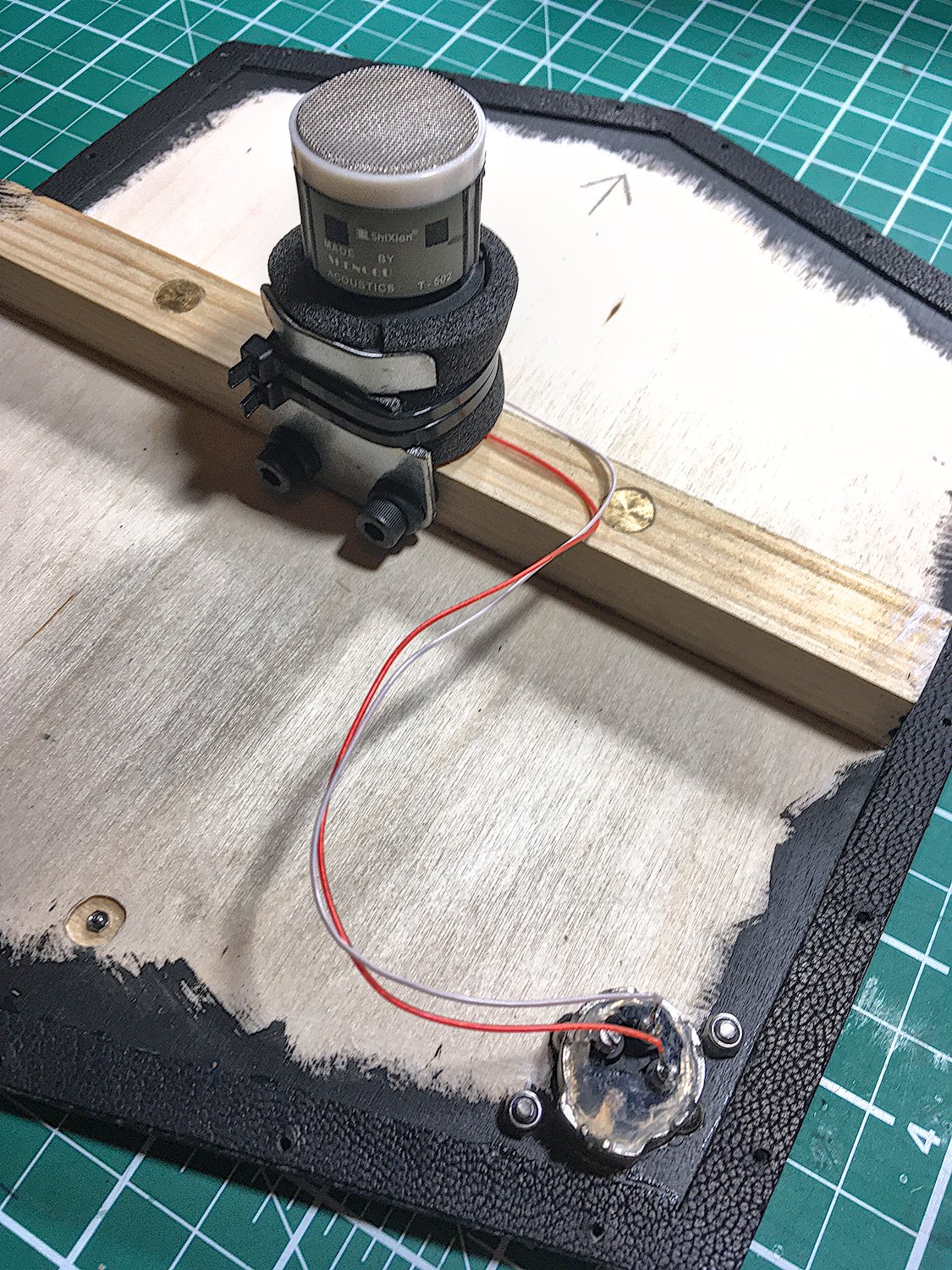
Sixth attempt: after discussing and sharing audio recordings with my client, what we decided to do was to reinstate the internal dynamic cartridge and also come up with a way to mount the lavalier outside the bellows. That way the distorted but feedback-resistant internal dynamic mic can be fed into the effects chain, and some proportion of the clean-sounding dry signal from the external lavalier mic can be mixed into the output.
I modified the internal arrangement slightly; rather than solder the cartridge directly to the panel mount socket, I added an internal inline socket to make things a bit more modular.
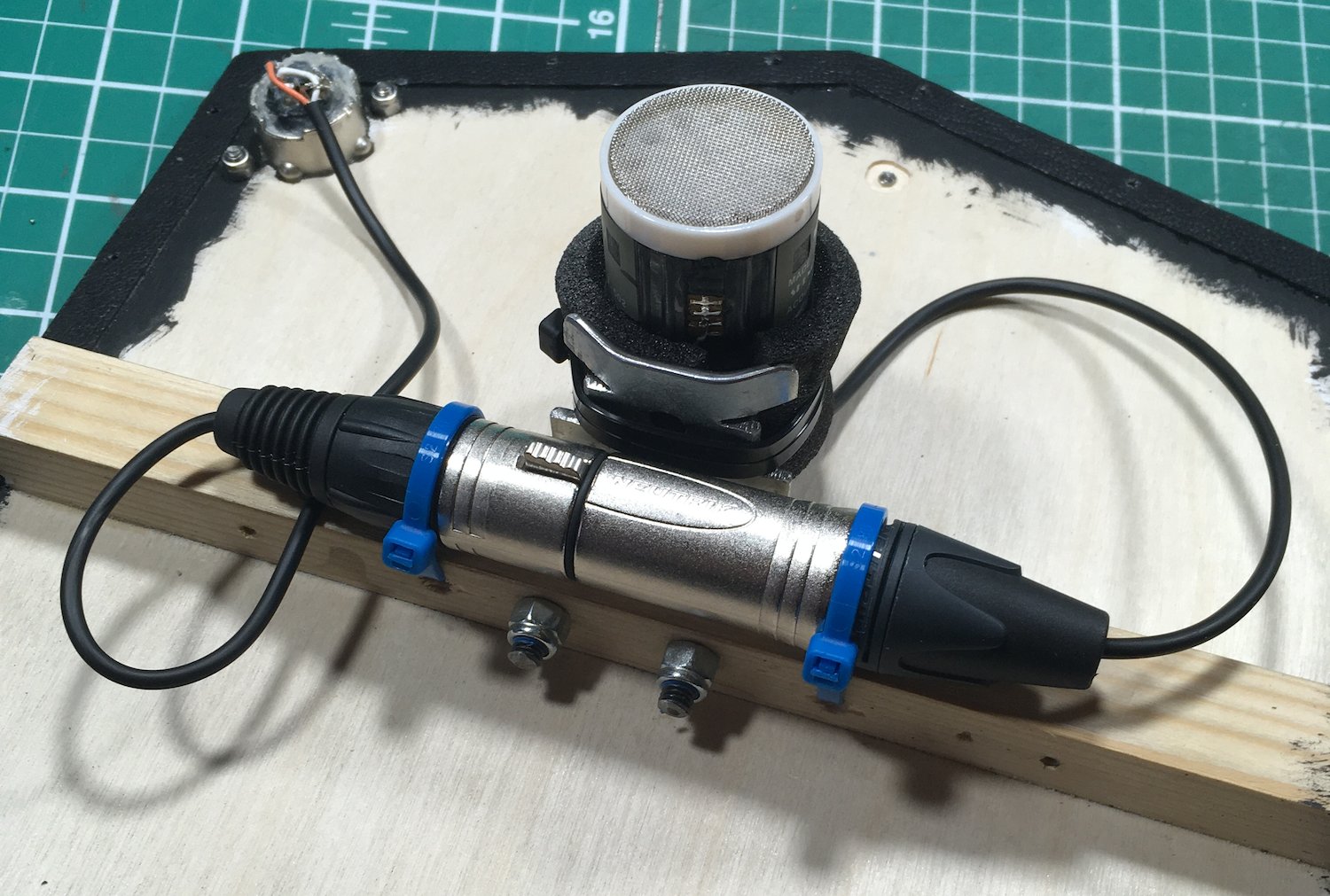
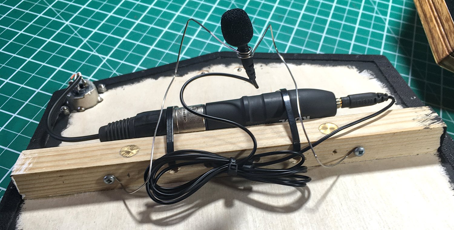
I mounted the XLR adapter to the outside of the blank end with a couple of aluminium brackets.
I threaded the mic through a fretwork piercing and attached it to the inside with some stainless steel wire.
This was also a mistake. It turns out that if you put an electret mic capsule inside an action box, the various clicks and taps and pops of the levers and pads become much louder than if the mic is outside the action box, the tone is a bit weird, and the sound levels from the pads close to the mic are quite a bit louder than those on the opposite side of the action board.
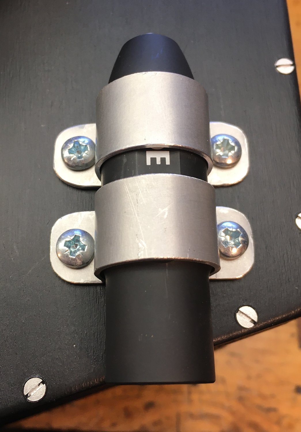
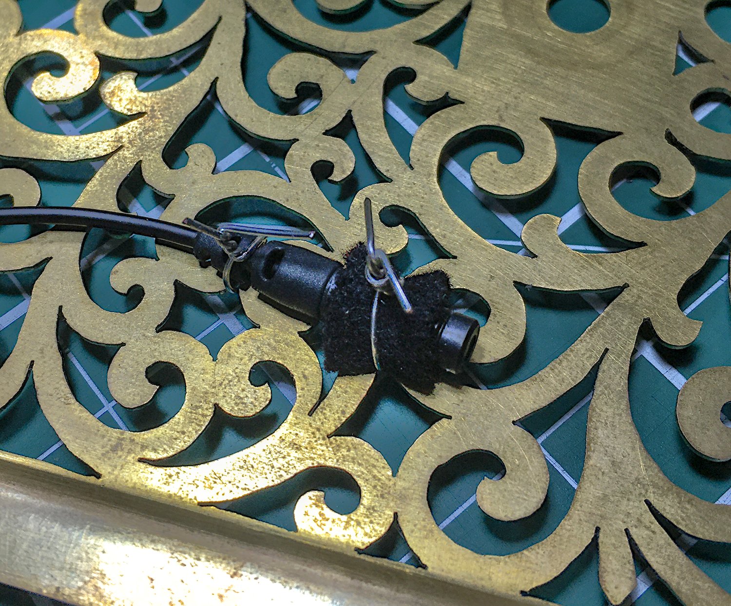
Seventh and final attempt: I took the mic back out from inside the action box and tried holding it in various places near the end while playing notes and listening to the mic live through headphones. I found a reasonable compromise in terms of balance was to place it close to the base of the thumb (when playing right-handed). The mic came with a lapel clip, so I made a removable leather-covered brass L bracket that bolts to the end plate and provides something to clip the mic onto. The idea is that the adapter and the bracket can remain semi-permanently bolted to the instrument but the mic itself can be stored separately and only attached when it’s actually being used.


The sound quality from the external lavalier is pretty decent, and although I didn’t like the sound from the internal mic, I have since heard from my client that it works pretty well as a pickup for the effects pedals.
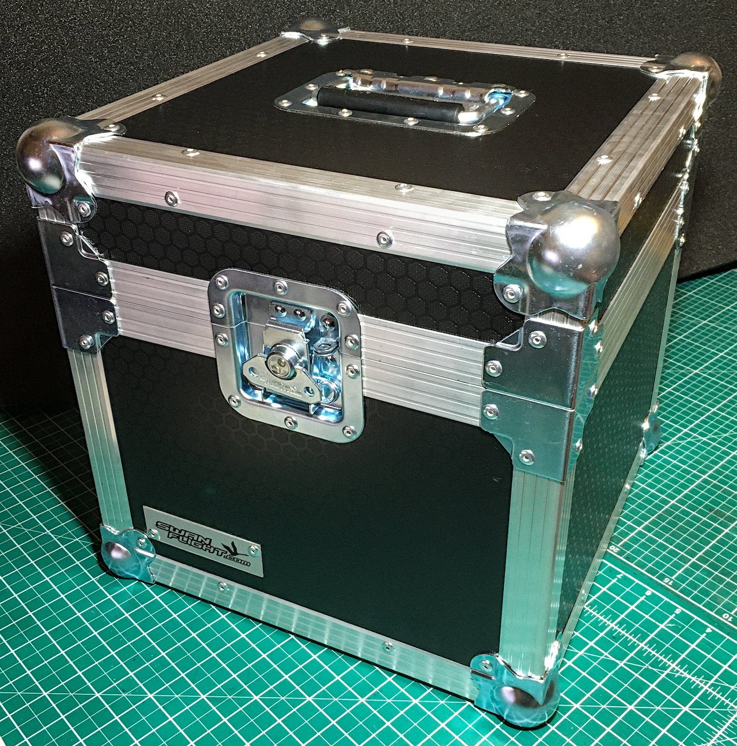
Case
The case needed to be sturdy enough to survive touring. After some thought and research we decided to go with a professional flight case. Rather than have one custom made, I found the SwanFlight LP100 (made to hold 100 12″ records) was only a bit oversize. It isn’t the most beautiful or lightest case I have supplied with an instrument but I think it might the most robust.
I ordered it without the usual lining, and made my own from thick EVA foam.
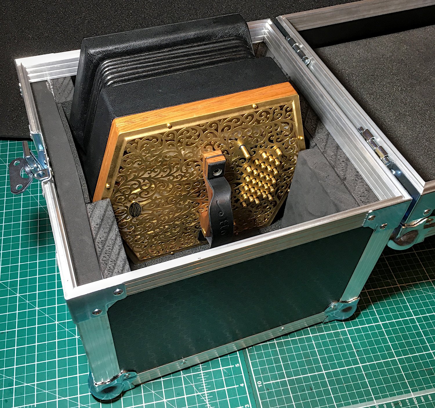
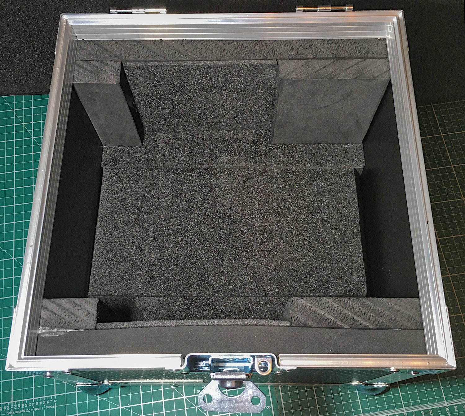
A section of the floor lifts up to reveal hidden compartments that hold various maintenance tools and the L bracket for mounting the instrument to a bench.
