Tools

Small Roubo-inspired Pine Workbench

I’ve just finished building a new workbench for my concertina-making workshop. bench1

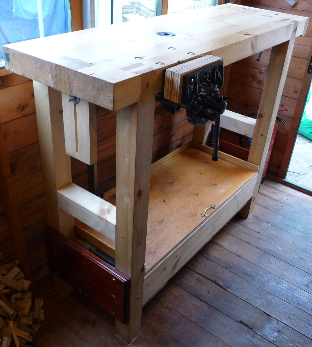
I designed it myself, loosely based on an 18th century French design described by Andre Roubo. Although mine is much smaller, made from construction-grade pine, and has modern (ish: they are probably older than I am) cast iron quick release vices instead of a wooden leg vice, they do have several important elements in common. The joinery is very similar, particularly the unusual dovetailed tenons that allow the legs to come flush with the edge of the top. It has a planing stop, a front vice, a holdfast, and a tool tray between the stretchers.

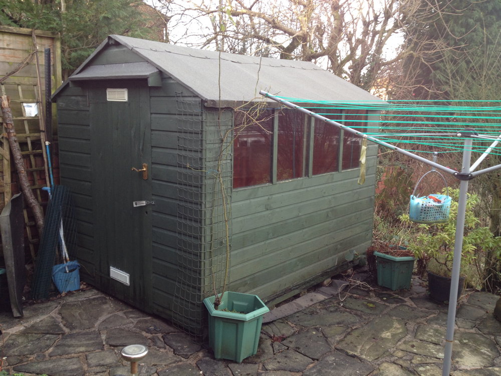
I made it 1m tall, which is on the high side for workbenches, because I mostly do fine detail work on small components, often under magnification, and in these circumstances a high bench reduces back ache from constantly bending over. The top is 400mm deep by about 1.2m long, which I felt was the biggest I could comfortably fit in my small garden shed workshop while also fitting in a coal stove to the left of the bench and two machine tool stands along the back wall.

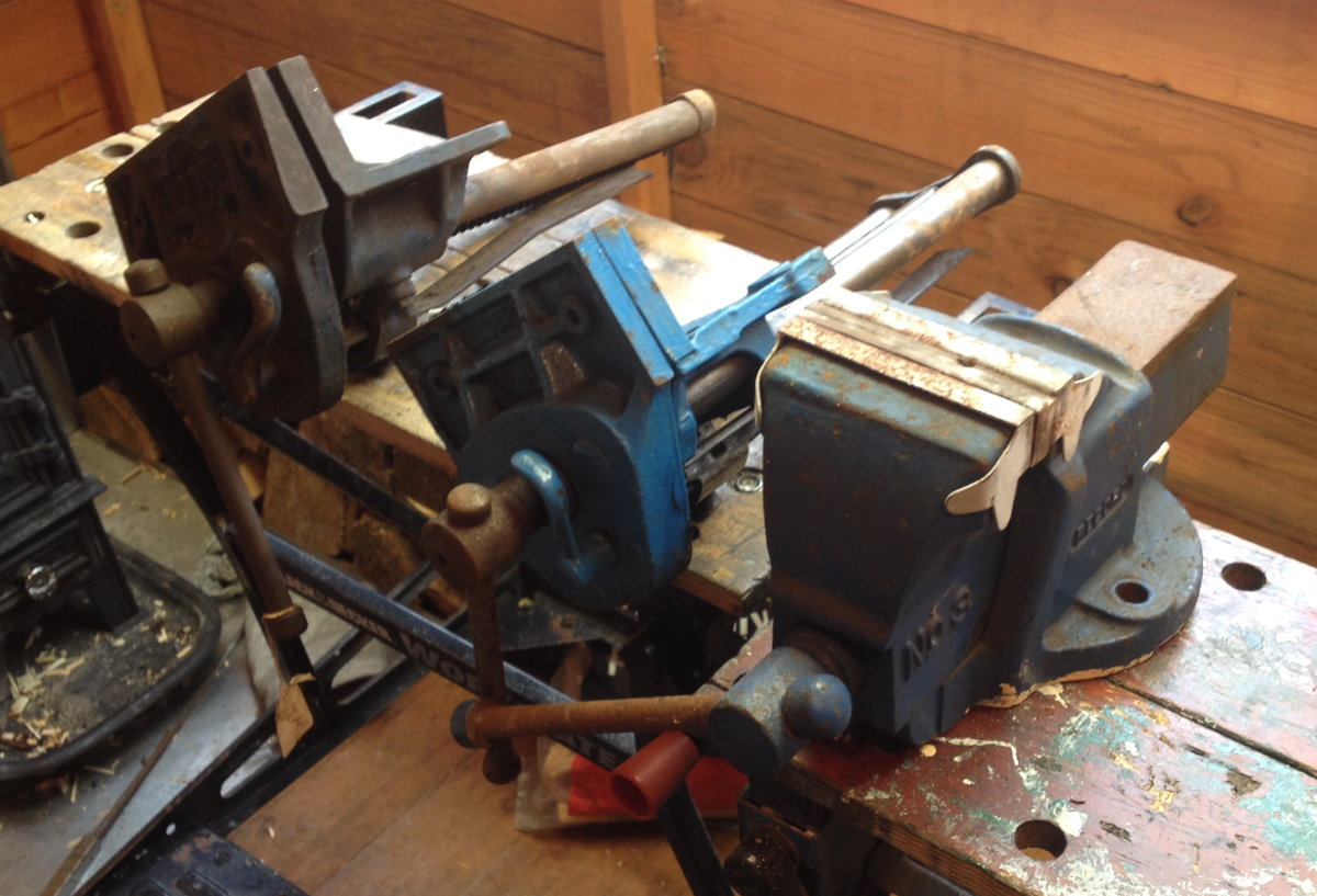
The next few pictures show a few of the many workholding options available to me on this bench. The Woden quick-release front vice with leather-lined jaws is likely to be my main workhorse:workholding1

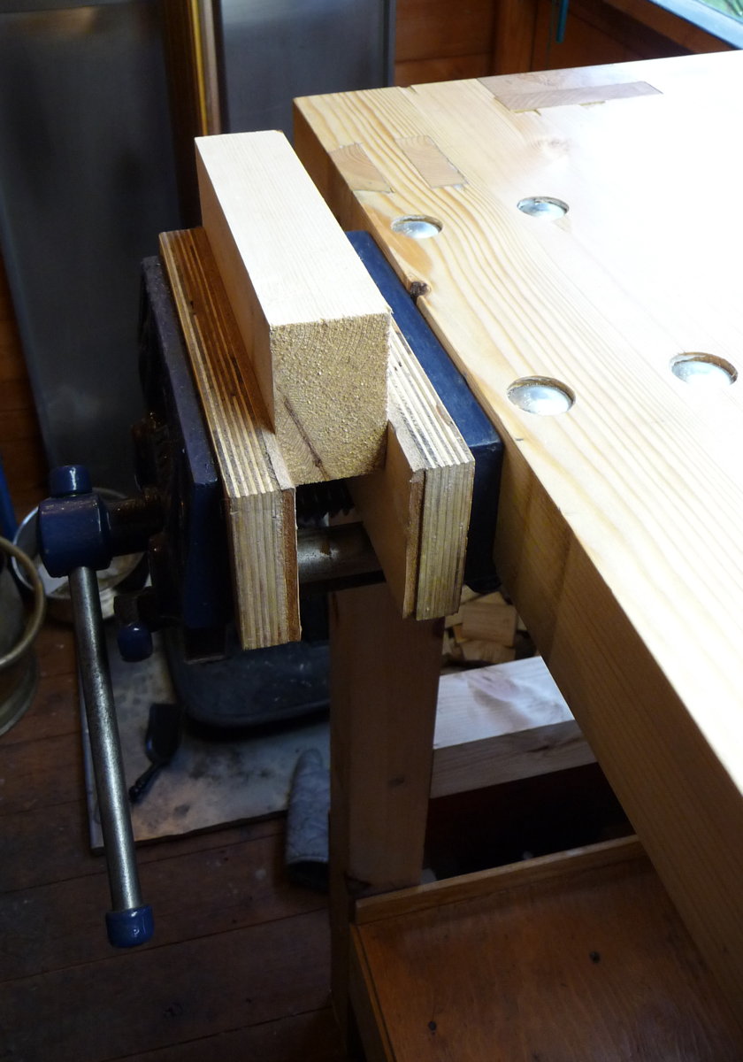
I also have a very similar Record quick-release vice, which I installed as a central tail vice with leather-lined wooden jaws that span the full width of the end of the bench. This idea is a bit of an experiment on my part, but I have a feeling it is going to come in handy (obviously I will have to be careful to avoid clamping things too far off-centre as excessive racking force could damage the vice).workholding2

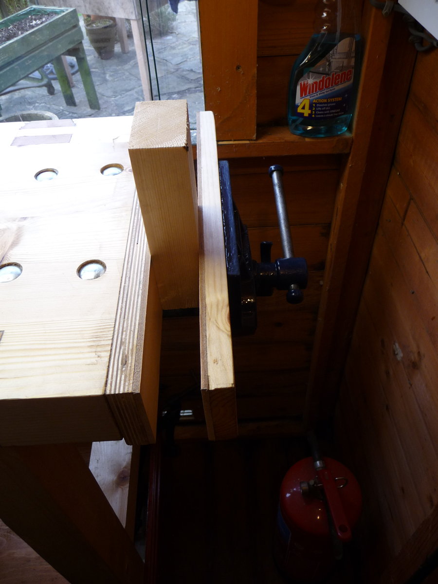
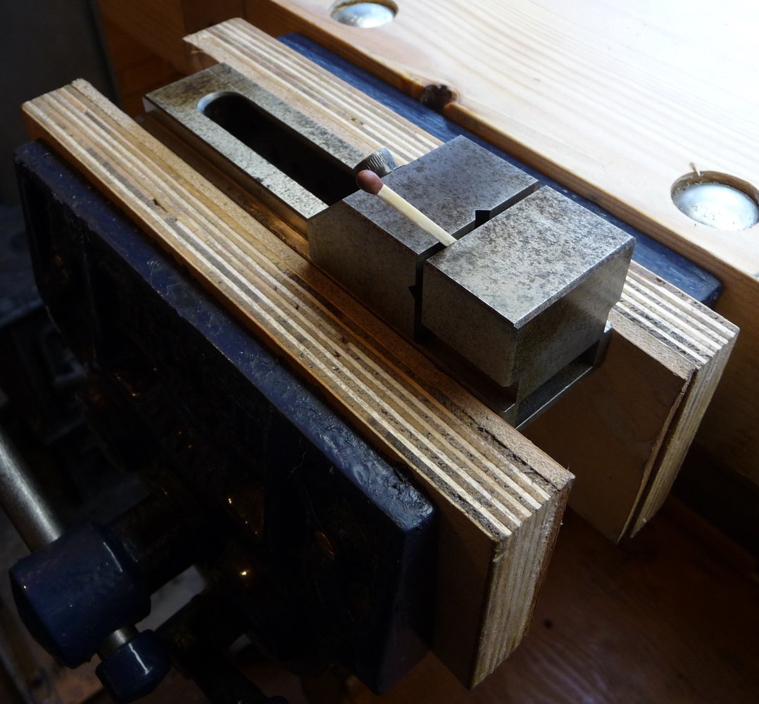
For light metalwork, I welded up a steel bracket that allows me to hold a Record No. 3 in the jaws of one of the woodworking vices (I’ve since painted the bracket the same colour as the vices):workholding3

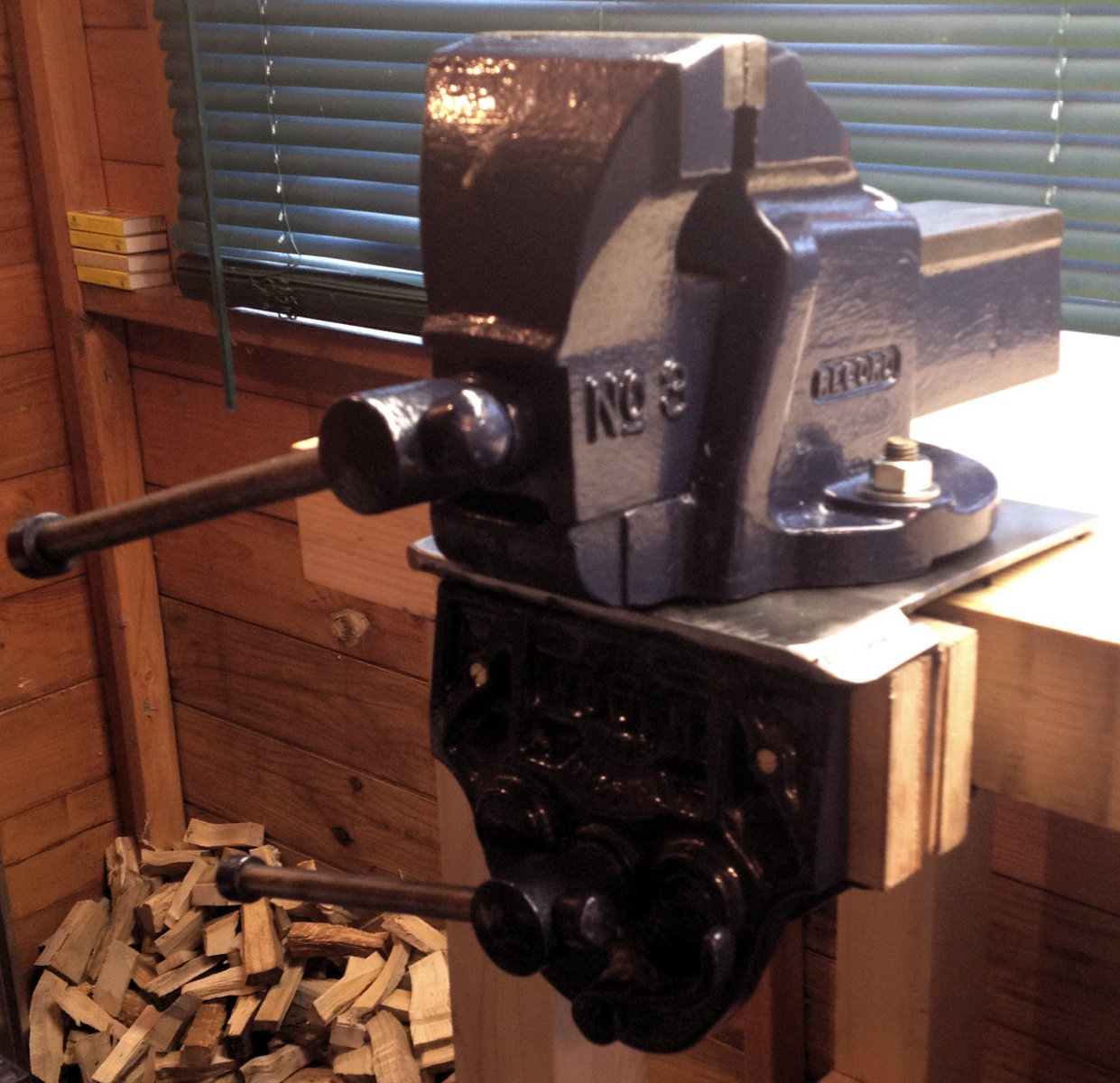
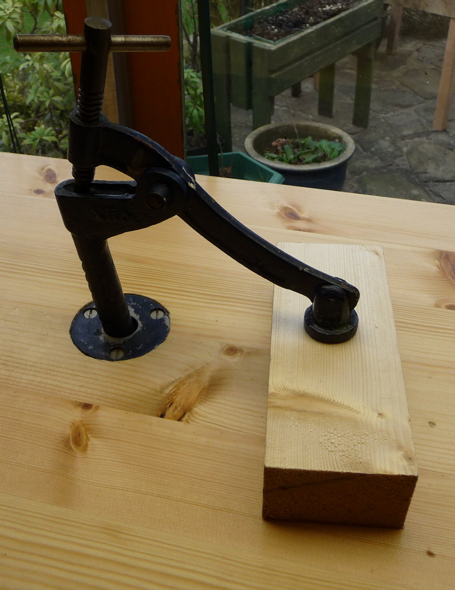
The holdfast is an important feature of Roubo’s workbench. Instead of the traditional forged iron bar that wedges into a hole when you hit it with a mallet, I went for a Woden hold-down clamp that performs pretty much the same function but with a screw to control the clamping force. It fits into a special tall cast iron collar with ridges inside that mate with notches on the back of the vertical rod, and it only came with one collar, so I put a lot of thought into the most versatile place for it to go on the bench.
workholding4

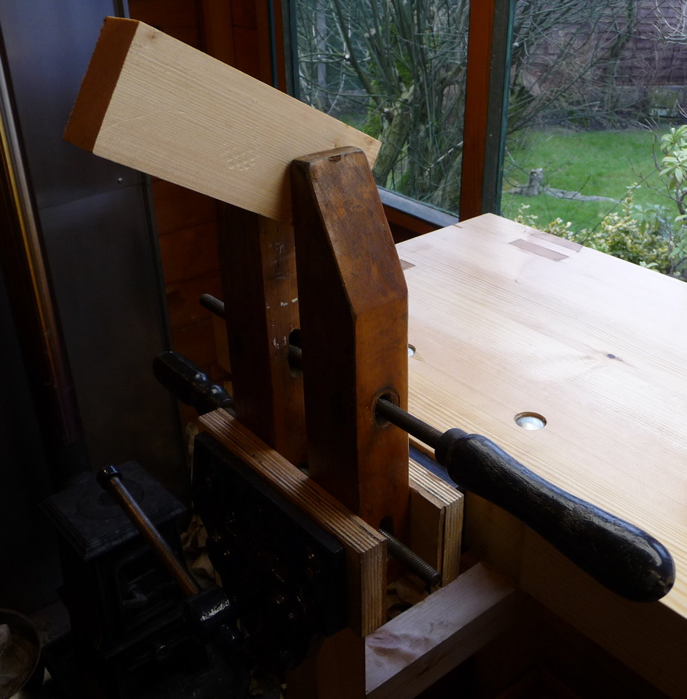
Another important feature of Roubo’s bench is the adjustable-height planing stop. Mine is a significantly different design, though it performs the same function. I made it from a limewood board without any metal teeth on the top, partly to avoid marring the work but mainly because I don’t want to risk accidentally running into it and damaging the plane, particularly when planing very thin stock. There is a wing nut under the bench that allows it to be clamped at the desired height.workholding5

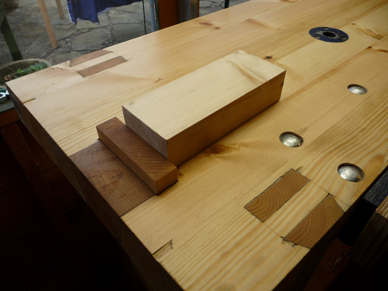
A feature of Roubo’s bench that I didn’t copy is the crochet; the hook on the front that you would use to wedge the end of a long board when jointing. It didn’t really make any sense given the fact that I can’t easily remove my front vice, which in any case can easily be used to clamp the end of a long board.

I also have various clamps and small vices that can be held in the bigger vices to hold things in creative ways:workholding7

workholding9

workholding8

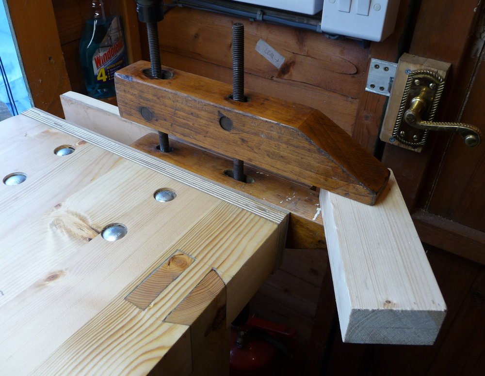
I don’t yet have any bench hooks or shooting boards, though I plan to make some soon.

The idea of the tool tray under the bench isn’t permanent storage, it’s just somewhere convenient to put down tools that you aren’t currently using, other than putting them on the bench top itself where they get in the way and risk being knocked onto the floor. I modified the idea a bit though, by putting mine on hinges with a storage box underneath it:bench2

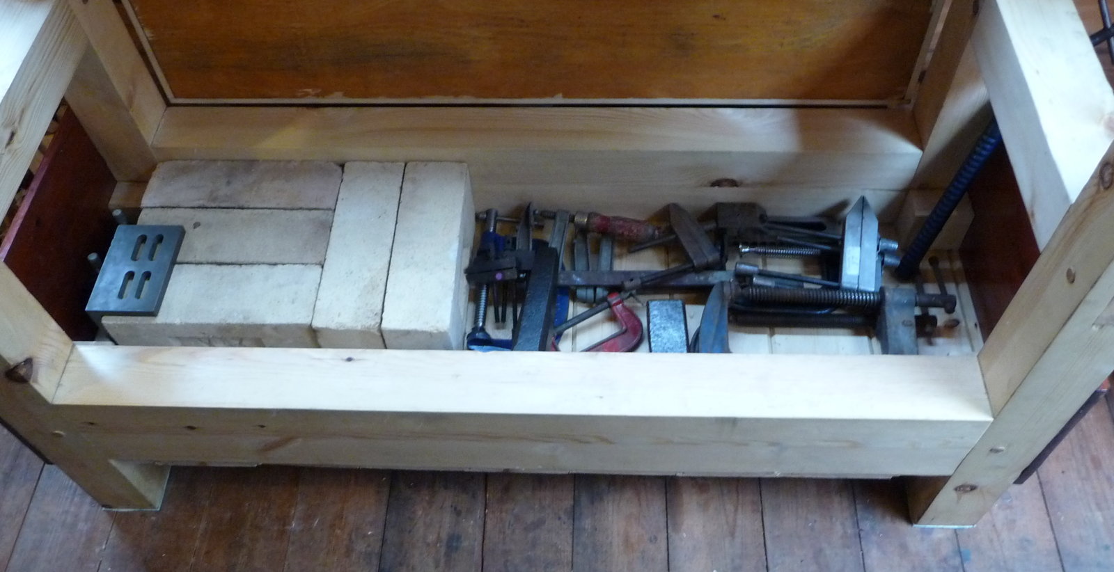
My plan is to store heavy things in here, thus lowering the bench’s centre of gravity and making it more stable. Currently it contains five fire bricks (!), a bunch of metal clamps, and a couple of small anvils. Combined with the fact that the bench structure itself is very rigid, the two other things I did to stop the bench moving around in use were that I glued rubber pads to the bottom of each leg and I attached the tops of the legs to the wall of the shed with angle-iron brackets, after bolting a steel channel to the wall to make it more rigid. I’m very pleased by how well this has worked.

Light is extremely important for fine detail work of the sort found in concertinas. Of course I put the bench next to the window to pick up what natural light I can, but that isn’t much use when it’s dark outside! The ceiling is too low for a conventional fluorescent light tube above the bench, and spotlights are problematic because they cast light and dark areas. After a bit of research I found out about LED light panels. I bought a 300 x 1200mm 40W daylight panel and fitted it directly above the bench, and I was amazed by the quality of light it produces. It is like being directly under a skylight on a bright day.ledpanel
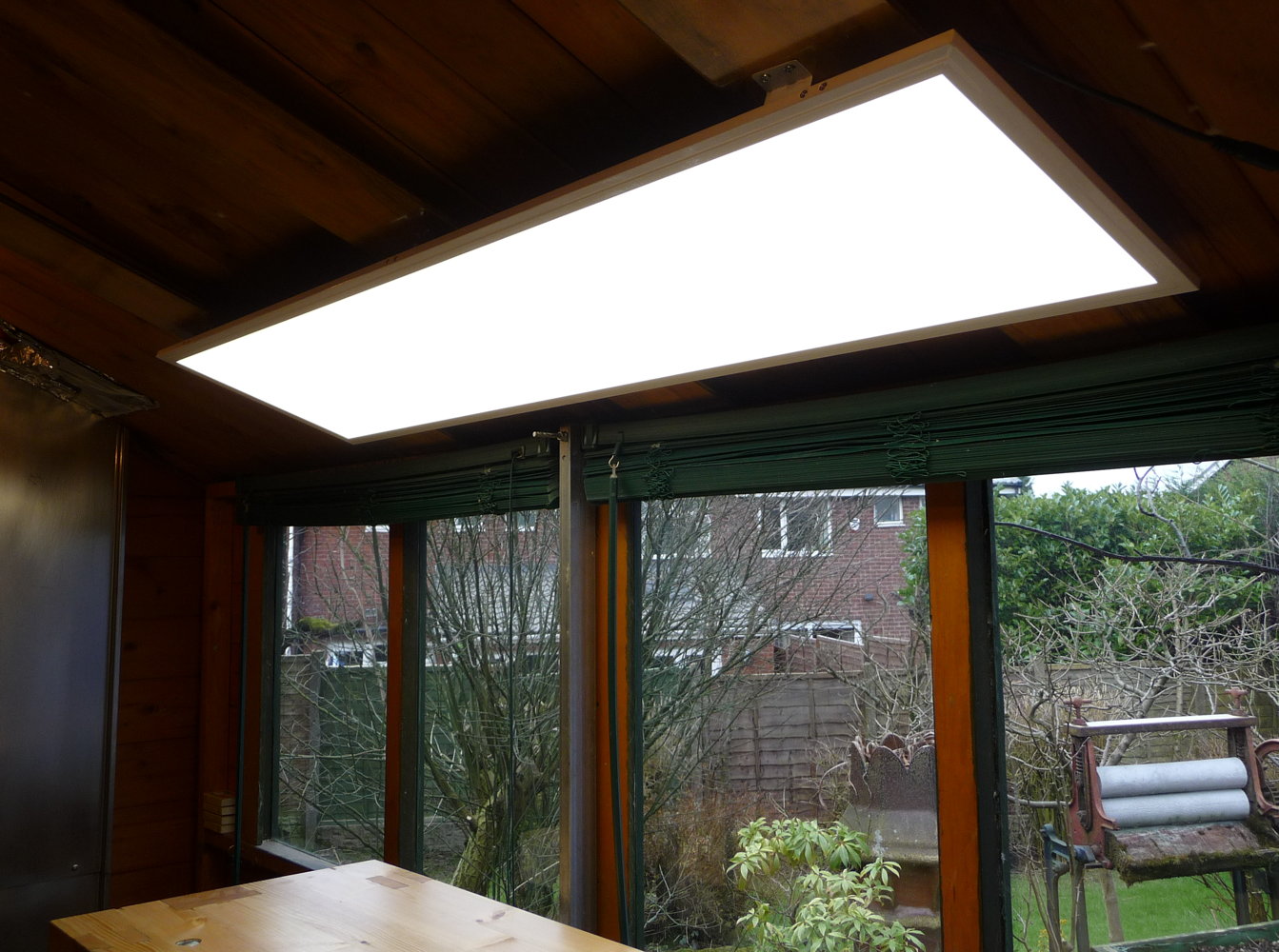
(On the negative side, I also replaced the bulbs in the two batten light fittings with newfangled LED filament bulbs, and I found those to be a bit disappointing: slightly dimmer than the claimed equivalent tungsten bulb, with a very dim patch directly below the bulb).

To finish up, here is a selection of pictures from the construction process.

The wood I bought to construct the bench, mainly 3″ x 3″ planed “redwood” (i.e. Scandinavian pine). IIRC it cost about £40 including the T&G on the left that I used for the bottom of the tool box (the lid was a piece of scrap plywood I had lying around).benchbuild1

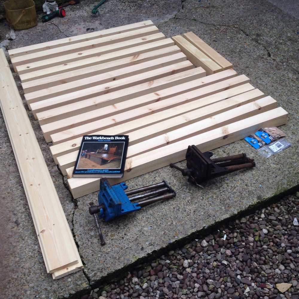
First I had to restore my Record No. 7 jointer plane, which I had never really had a use for before now, not being a furniture-maker.benchbuild2

benchbuild3

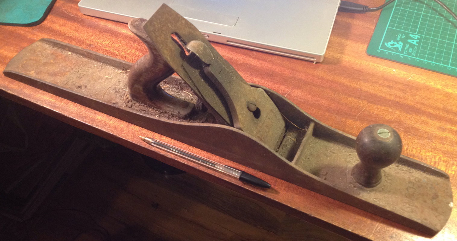
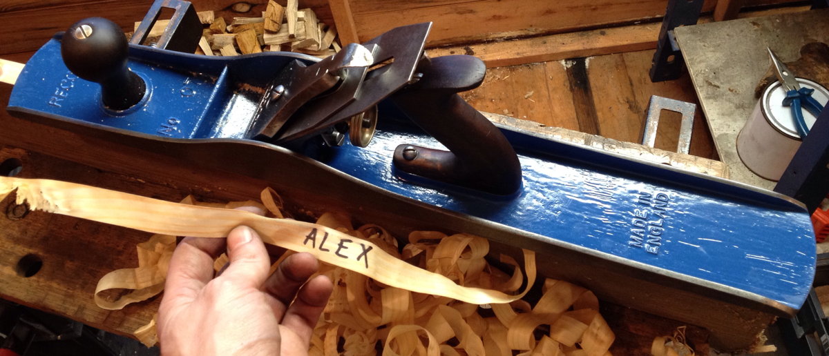
Then I used it to joint the boards that I glued together to form the long stretchers and the top:benchbuild4

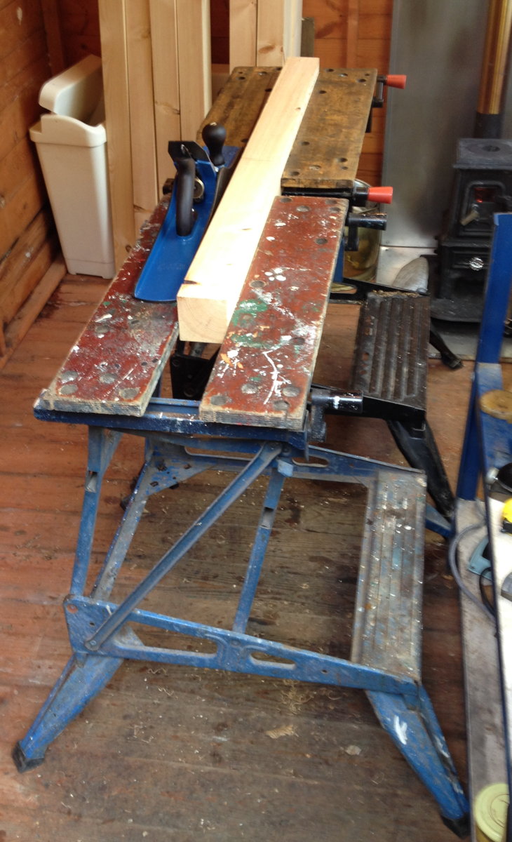
I glued one joint at a time using hot hide glue and three sash cramps (it might have been preferable to use a couple more, but I was horrified when I found out how much decent ones cost). My vintage electric iron was used to preheat the wood to extend the glue’s open time.benchbuild5

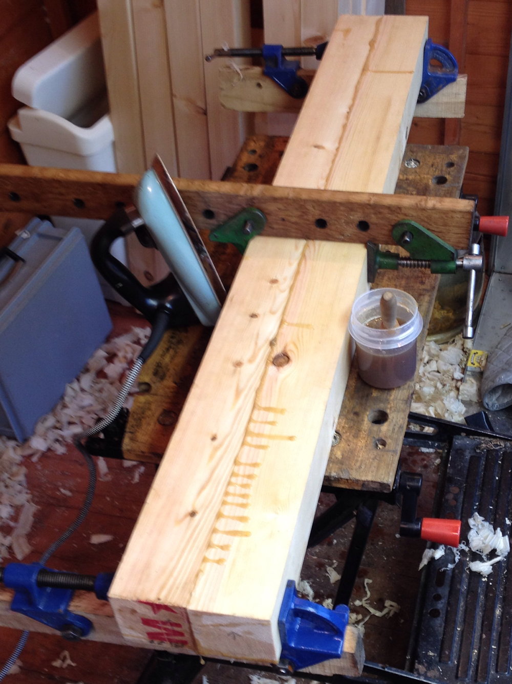
After the top was fully glued up, I roughly trued and squared it with a wooden jack plane:benchbuild6

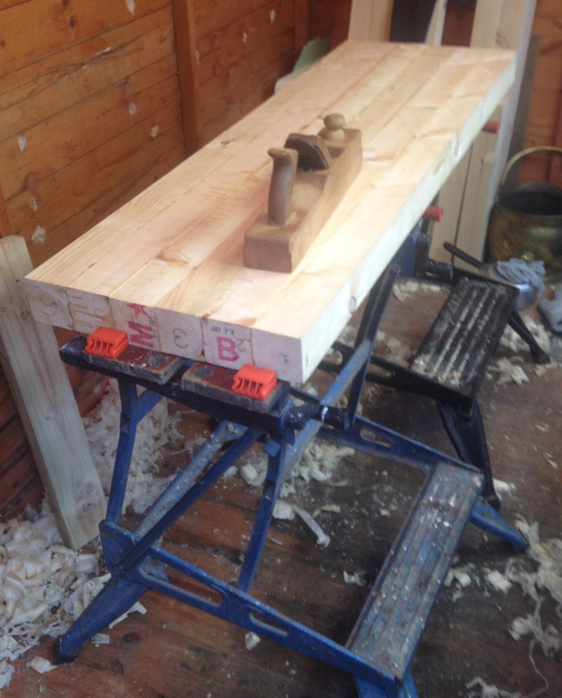
Then I flattened the top surface with the jointer plane. After final assembly I re-flattened it, and was surprised to discover that in the intervening couple of weeks it had cupped by about 2mm.benchbuild7

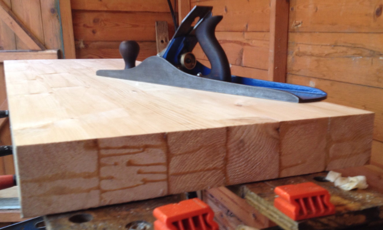
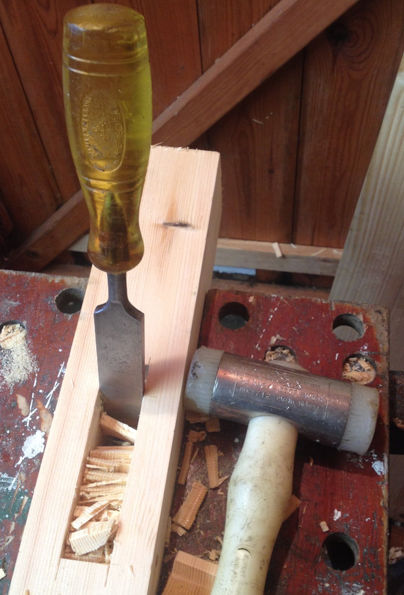
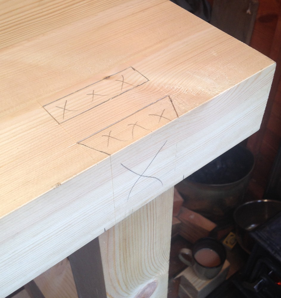
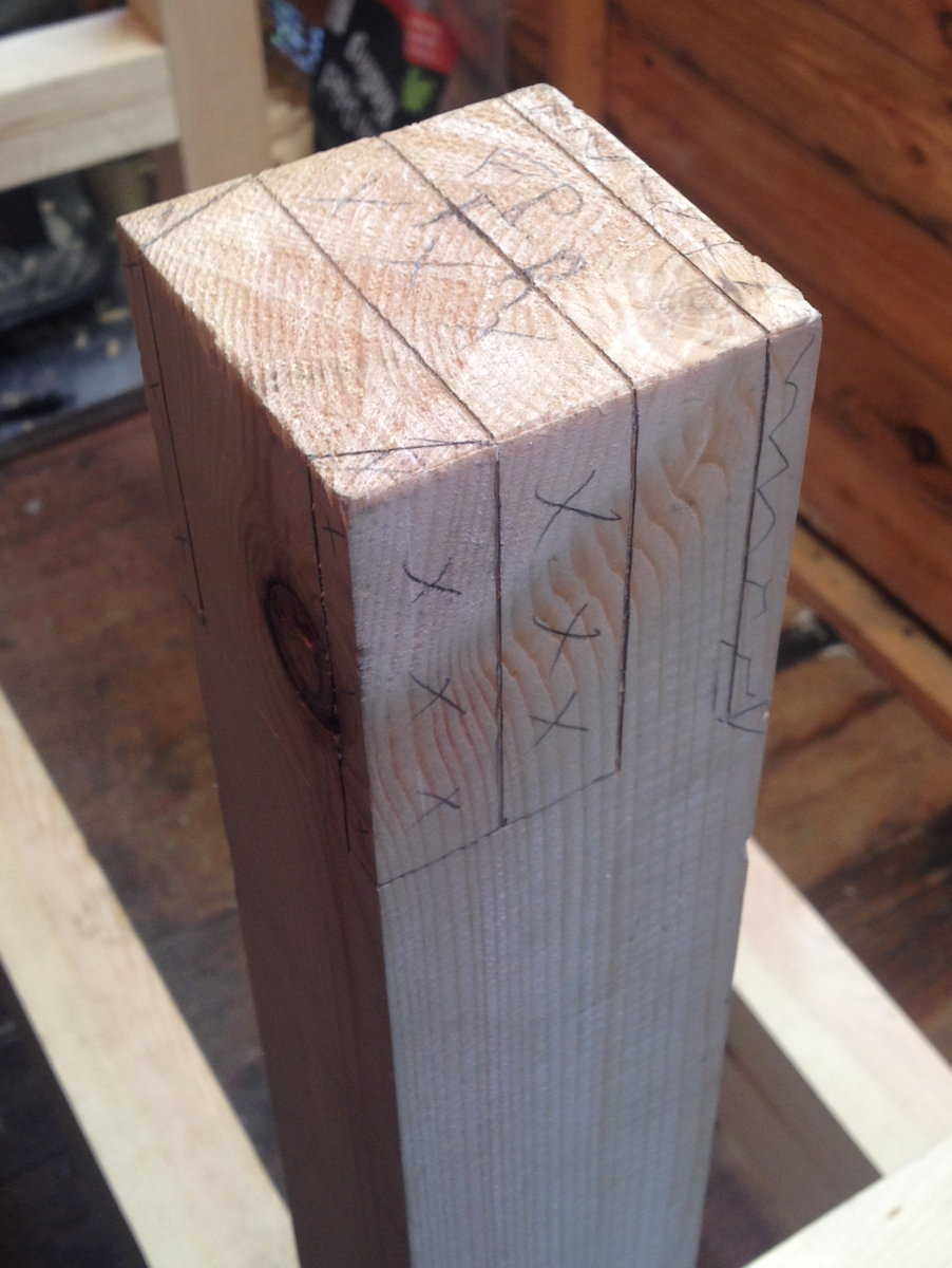
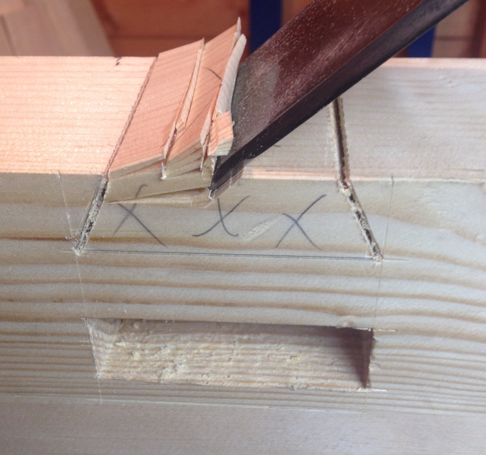
Cutting the joinery:benchbuild8

benchbuild9

benchbuild10

benchbuild11

benchbuild12

benchbuild13

benchbuild14

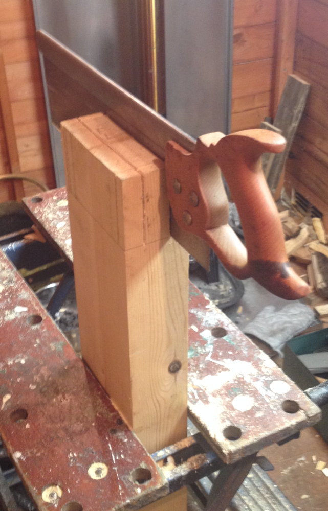
First assembly of the bench, with Pippin the pushme-pullyou dog (this was an accidental trick photo caused by my dad activating the panorama feature on my iPhone).benchbuild15

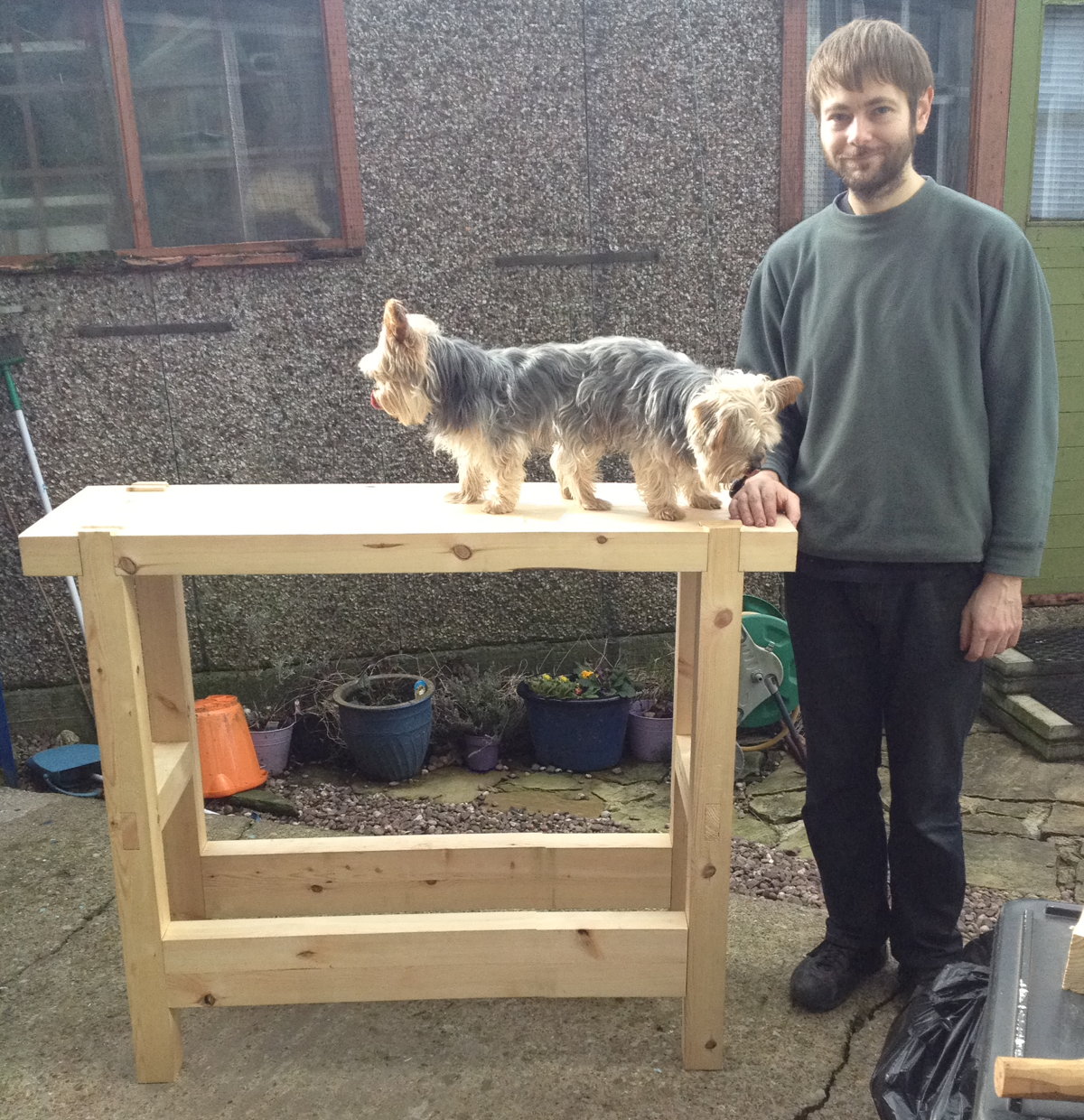
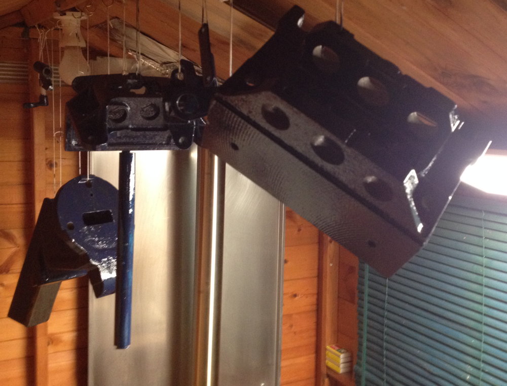
All three vices needed a good cleanup and repaint. The Woden vice also turned out to have had the quick release mechanism modified in an inexplicable way that prevented it functioning – after reversing the bodge it worked fine.
benchbuild16

Annoyingly the new paint didn’t dry very well at all, and after several days I got fed up waiting for it to harden and fitted them anyway, resulting in the very soft paint rubbing off in a few areas.
benchbuild17

Making riven beech pegs to hold the joints together. I didn’t use any glue, or even bother to drawbore them.benchbuild18

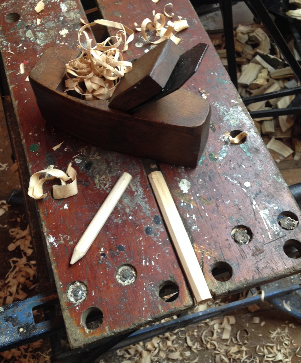
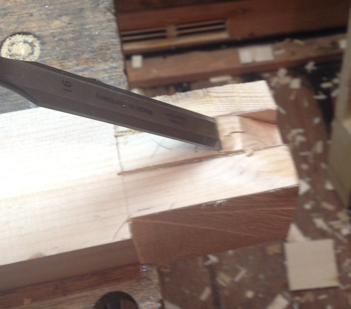
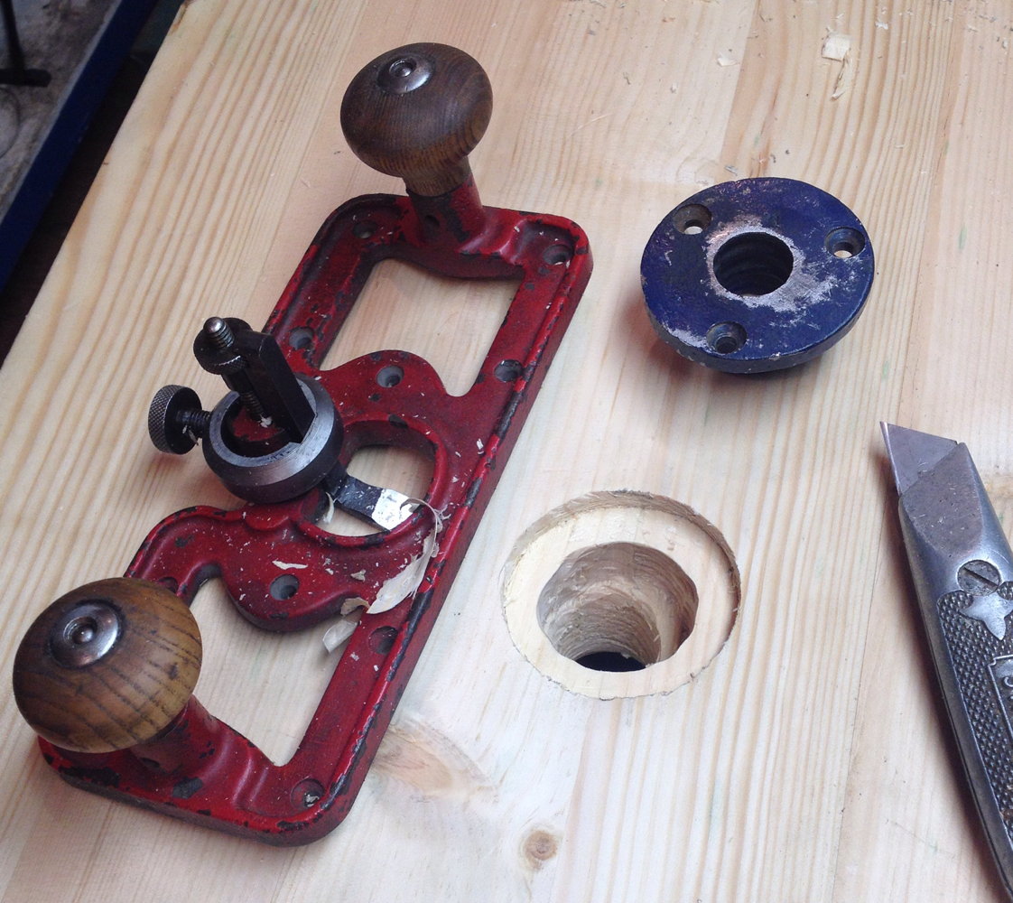
Setting the hold-down collar into the benchtop using my router plane.
benchbuild19

The fixed jaw of the end vice was morticed into the benchtop to avoid having a gap between the end of the bench and the wooden jaw.benchbuild20

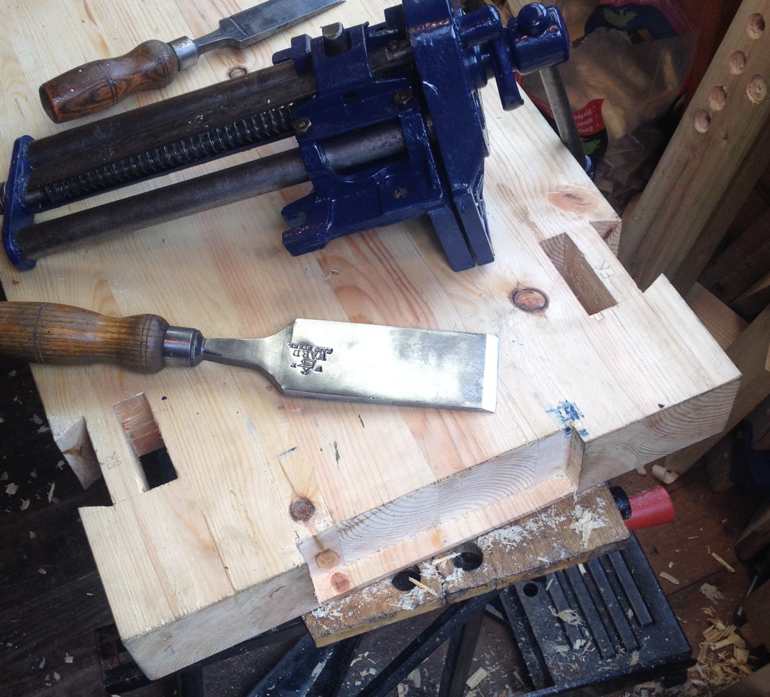
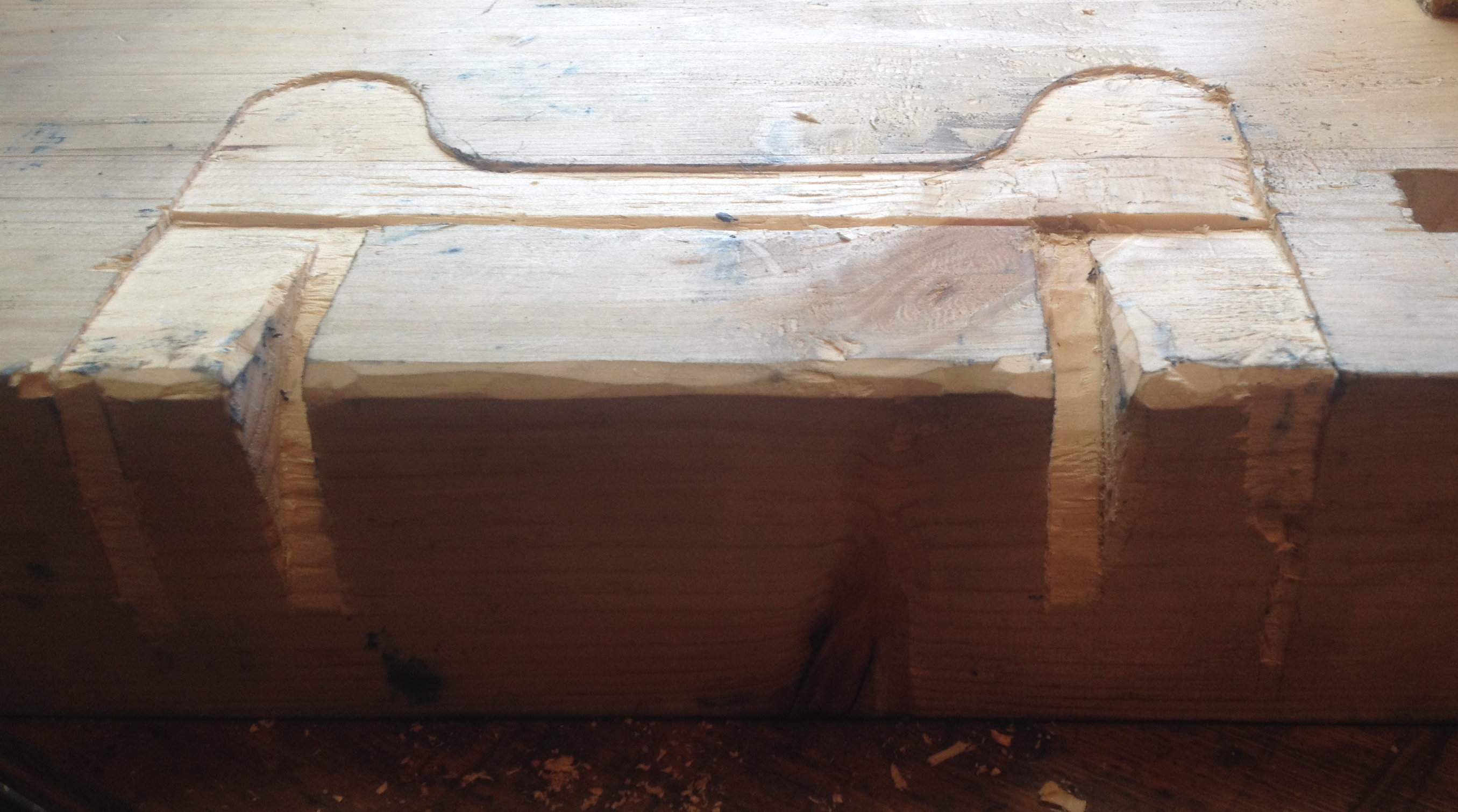
Unlike the Record vice, the Woden one had a really rather wonky top surface where it bolts to the underside of the bench.
benchbuild21
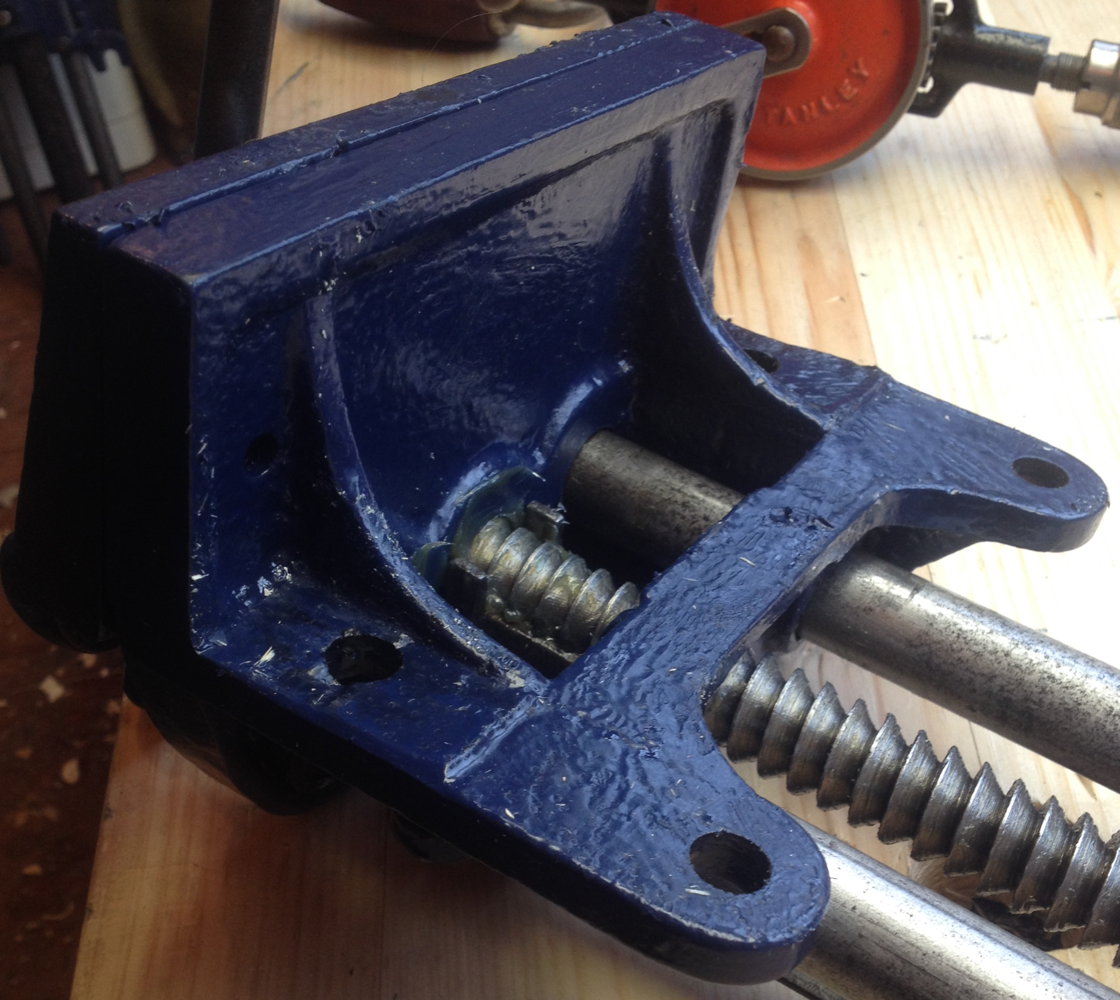
As a result, I had to spend a couple of hours painstakingly carving the underside of the bench to match the top of the vice in order to get it to fit snugly and not rock:
benchbuild22

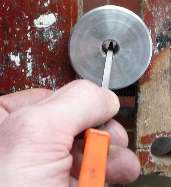
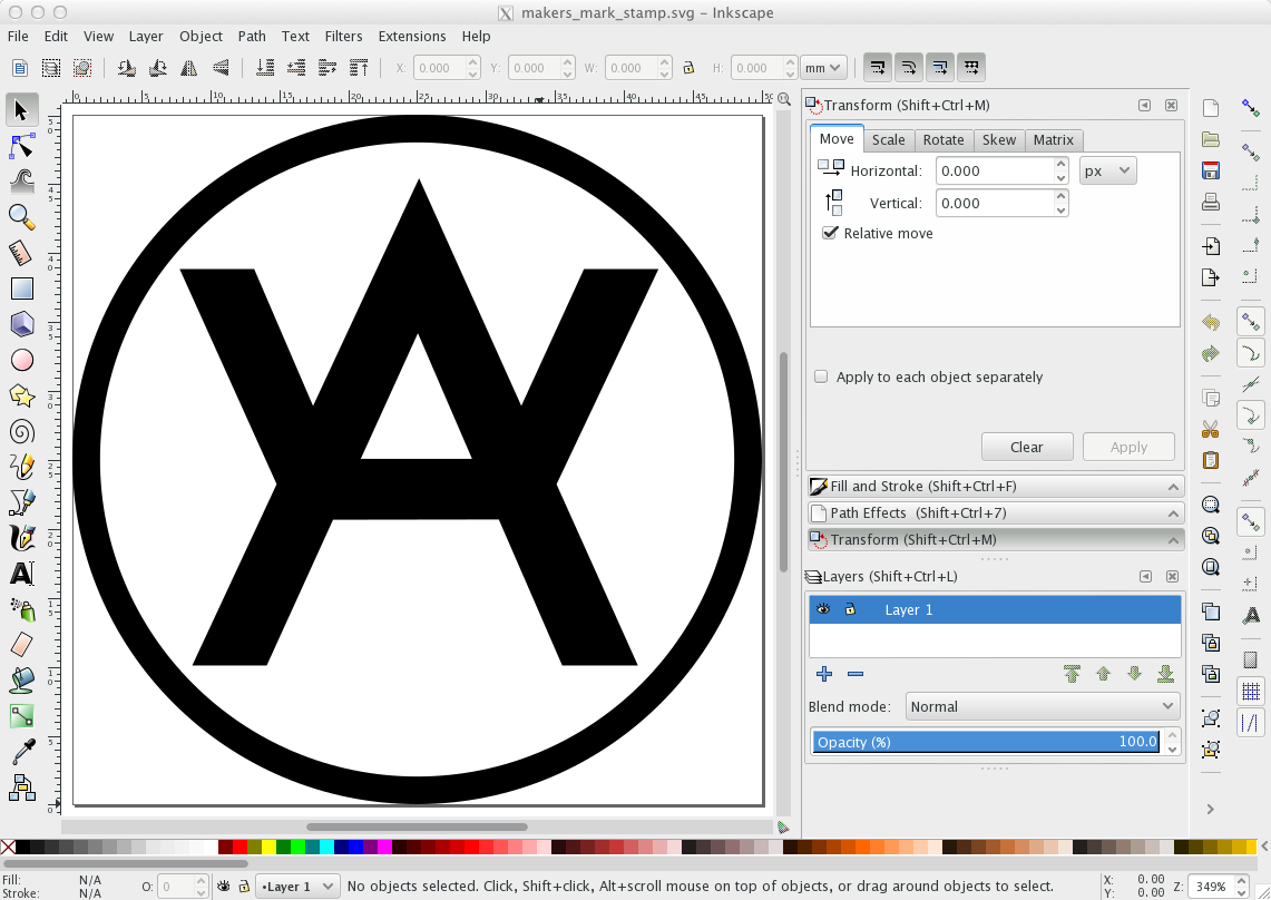
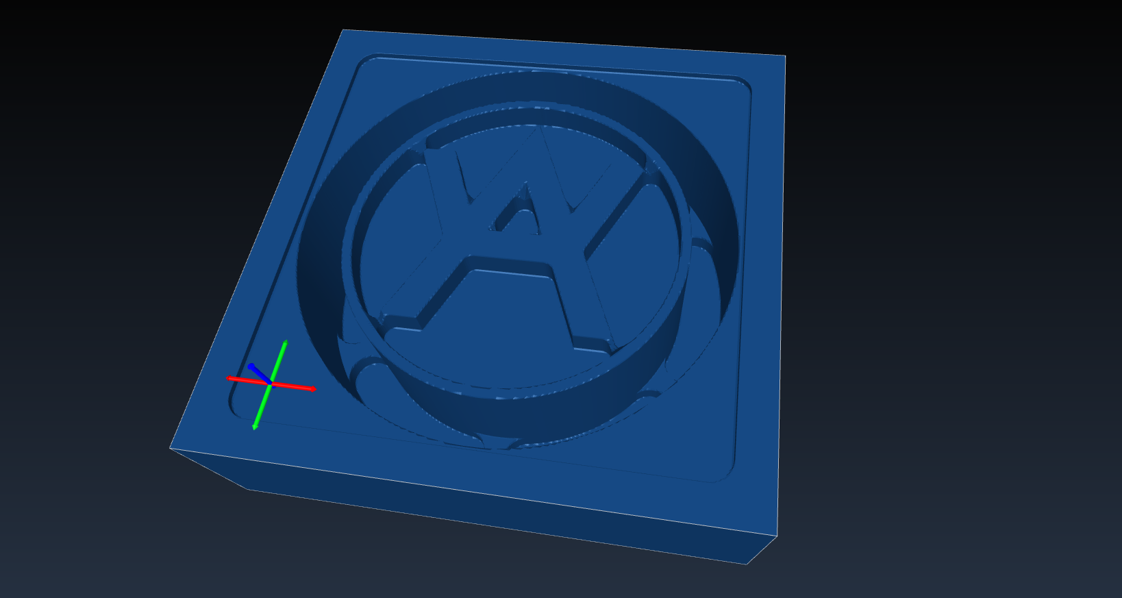
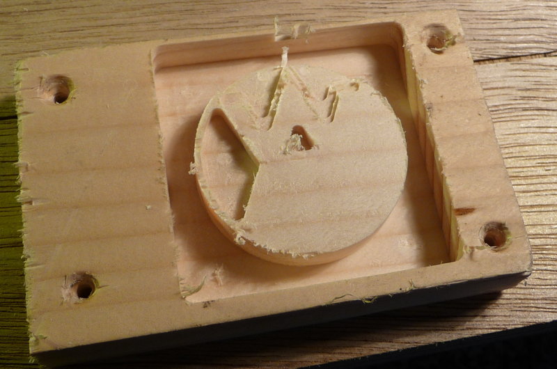
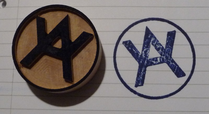
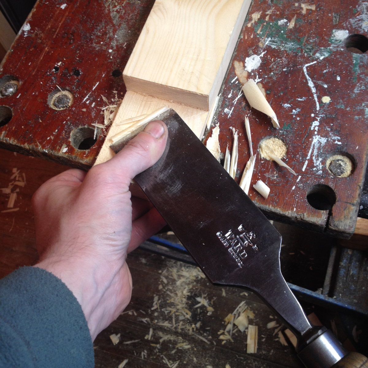
Before I finally attached the top to the legs, I whittled my maker’s mark and the year of construction on the underside:benchbuild23

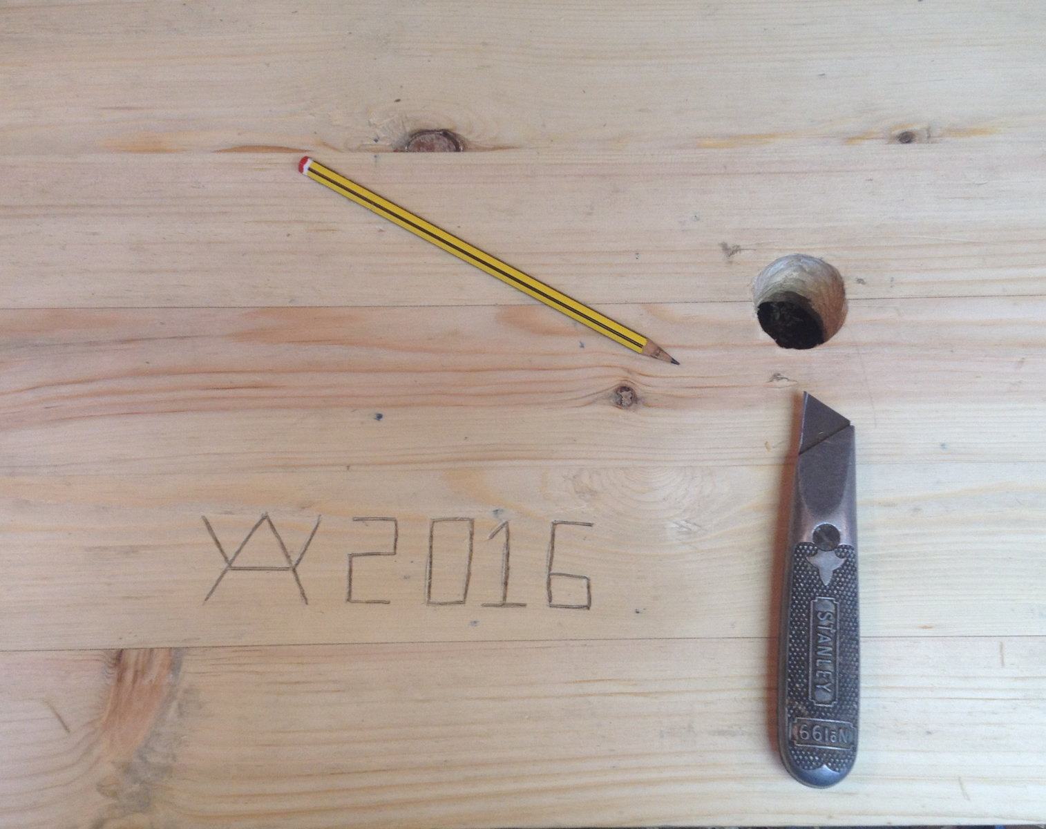
The long stretchers were held into the legs with both a peg and a pair of wedges (which open the tenon out into a deliberately tapered mortice). This is a very strong joint, even without glue. Getting the wedges out if I ever want to disassemble it will probably be a bit of a struggle though.benchbuild24

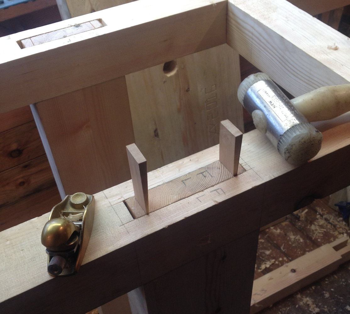
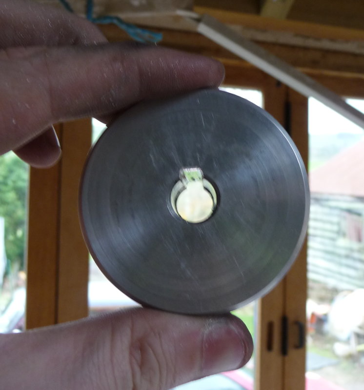
Simply screwing the hold-down collar to the bench top didn’t work very well; when I tightened the clamp the screws started to pull out, so I fixed the problem by making this steel clamp plate that goes on the underside of the bench. The screws are M5, stainless steel.benchbuild25

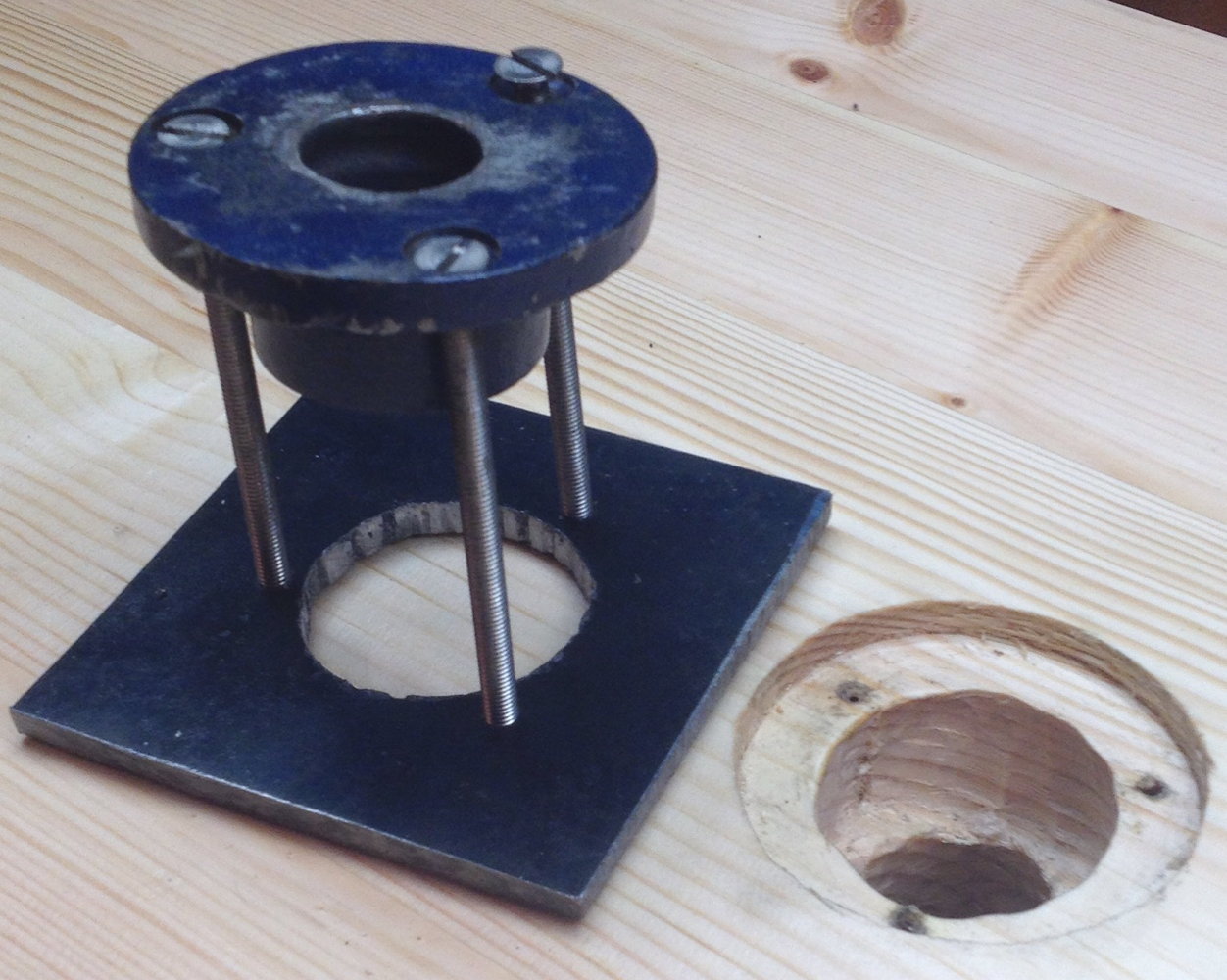
The short section of benchtop behind the planing stop shrunk and split after a few days, so I cut it out and scarfed in a chunk of dry oak instead.benchbuild26

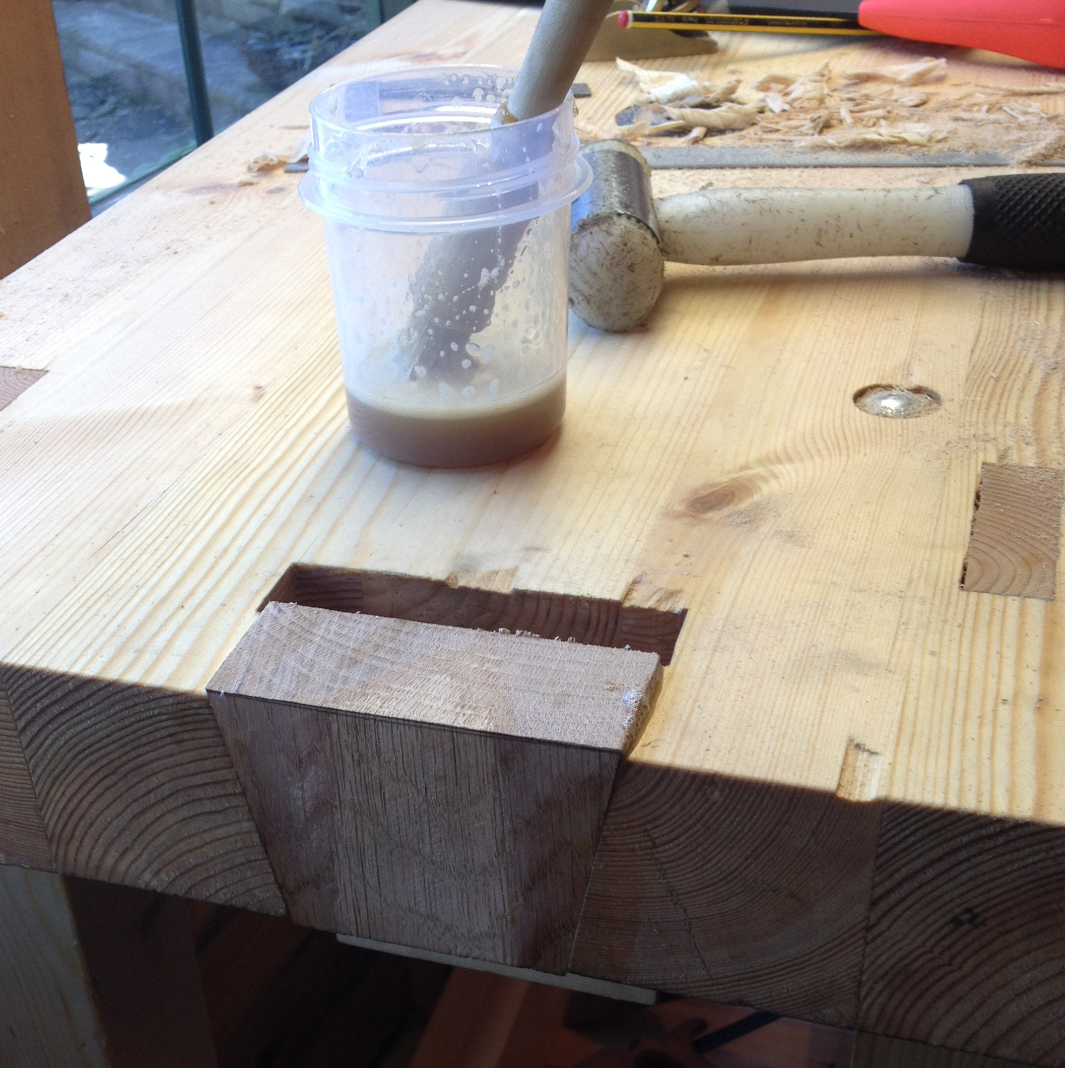
Small Roubo-inspired Pine Workbench Read More »

New Beginnings

I have moved back to Burnley! Soon I should be able to start making progress on building my first instrument. Currently my tools and materials are piled up in crates and boxes in my bedroom and garage, and my milling machine is broken down into several pieces, so my first task is to convert this damp 6×8 feet garden shed into a cosy little workshop:

shed_before

At some point I hope to save up enough money to replace it with something a bit bigger and more substantial that is designed from the ground up to be dry, insulated and secure. For now, my plan is to install a tiny coal stove (which can later be transferred to the new workshop), repaint the outside walls, add more ventilation, and store as little as possible in there when I’m not actively using it.

The first thing I intend to make in the new shop is a workbench. Nothing massive or fancy, just a solid pine worktop (made from a spare kitchen table I found in my parents’ loft) at a convenient height, secured to the floor/wall, with some old cast iron vices and a planing stop. After years of working on flimsy trestle tables and Black and Decker Workmates, it will be great to have a sturdy fixed bench that doesn’t skitter across the floor when I try to plane something. In a stroke of good luck, just as I was starting to think about workbench design, I happened to stumble across a copy of The Workbench Book by Scott Landis for a couple of pounds in a local charity shop. It’s a hefty book filled with inspiring ideas. My first self-built workbench probably won’t be my last, but seeing what other woodworkers are working on has helped me to identify more clearly what features I think I will find most useful for the type of work I do and avoid some things I might have regretted later (e.g. I don’t want any dog holes in the top: too easy to drop small parts down them).

Making concertinas from scratch requires a lot of tools. Metalworking, woodworking, leatherwork, and some very specialised things like a tuning rig. In addition, there are opportunities to speed up production if you invest in special tooling and machines. In order to try to avoid falling into the trap of Tool Acquisition Syndrome (gotta collect them all!), I’ve started categorising tools like this before I decide whether I need to buy one or not:

  1. Tool that is the bare-minimum cheapest way to perform an essential operation. For example, it’s perfectly possible to cut out fretwork ends using a cheap and cheerful bent steel fretsaw you can pick up for a quid or two at most car boot sales. I have a few of these in various sizes. They are a bit slow and tiring to use for long periods, but they are perfectly capable of producing excellent results.
  2. Tool that speeds up an essential operation. For example, a scroll saw is a machine that does essentially the same job as a fretsaw but can cut perhaps four times as fast with less physical effort. The difference is actually probably less significant with more complex designs because you spend so much of your time stopping and moving the blade to a new piercing. I have both a treadle and an electric scroll saw. I should probably get rid of one of them to save space, but I need to do some proper side-by-side tests before deciding which of them I prefer to use.
  3. Tool that is a higher quality version of something I already have. For example, my scroll saws are both hobby-grade machines: either will do the job for now, but certain features are inaccurate, fiddly and annoying to use, or not built to last. If in the future I find myself with the budget to upgrade, it would be nice to step up to a higher quality saw like a Hegner, or maybe even a vintage industrial machine.
  4. Tool that would be nice to have, but isn’t essential to concertina-making at all. I’m struggling a bit to continue with the fretwork analogy here. Let’s say an electric bandsaw: one could perhaps argue that it could be used to rough out the blank more quickly than with a handsaw, but it isn’t of any use for cutting the fretwork itself because you can’t get the blade inside a closed piercing (and they can’t cut very fine details and tight curves).

New Beginnings Read More »

Milled Boxes

It has become a tradition for me to make several Christmas presents each year using whatever tools/skills I have picked up most recently. This year my latest tool acquisition is the CNC milling machine, so I decided to do a project that would show off some of what it can do, as well as giving me some useful experience in programming it. A friend suggested trinket boxes. After considering various possible construction methods, I settled on milling them from blocks of limewood with thin plywood bases and lids.

I needed to make presents for three people. The nature of one-off CNC manufacture is such that most of your time is spent at the CAD/CAM stage, because you have to plan every detail in advance and figure out how to tell the machine what to do (being careful to avoid anything that is physically impossible, for example asking it to cut a 3mm wide slot when your smallest cutter is 3.175mm in diameter). It would have been easy to design one box and produce three exact copies, but where would be the fun in that? I instead decided to do three different designs. I learned new things from each one and I feel the third design is the best, so it wasn’t a wasted effort.

The CAM workflow was basically the same as with the maker’s mark stamp except the designs and machining operations were far more complicated. An additional step was deriving the profiles of the lids from the shapes of the rebates they sit in; this was complicated slightly by the fact that I needed to round off all the points because the internal corners of the rebates can’t be any sharper than the diameter of the router bit.

The milling operations themselves mostly went OK. I suffered one stepper motor stall while milling the first box, but I heard it happen and managed to hit the e-stop in the nick of time before it did any noticeable damage.

milling_box

routing_lids

I made one design mistake: one of the lids was cut to the wrong outline (you can see it in the next photo). I didn’t spot it at the simulation stage because it was approximately the right shape for the compartment, just slightly too big.

milled_boxes

When I cut the replacement lid I took the opportunity to make a little Christmas tree decoration at the same time:

snowman

The boxes looked pretty plain with ordinary birch plywood lids, so I bought a selection of patterned decoupage paper on eBay and pasted various combinations to the lids. I also pasted plain coloured paper to the bottoms.

pasted_decoupage

I turned the knobs by hand from beech. Because there was quite a bit of variation I made more than I needed and picked out sets that went well together.

turning_knobs

turned_knobs

Here are all three finished boxes after lacquering:

finished_boxes

The ‘S’ box is my favourite (made for my mum, Sandra):

s_box

I came up with the basis for the design while playing around with mathematical knots. It is based on the 8 18 knot.

Incidentally I now have an Instagram account and I’m using it to post pictures of things I’m working on.

Milled Boxes Read More »

New Stamp

I’ve been spending quite a bit of time recently working on my CNC milling machine and learning how to program it.

The main improvement I’ve made is to replace the spindle drive motor. The one that came with the machine was a 1/4HP single phase motor that ran at a fixed speed that gave me, on the top pulley ratio, something like 4000RPM at the spindle.

new_cnc_motor

The new one is pretty much the same physical size and weight (maybe a little bit lighter) but it is a 1/3HP three phase motor that, paired with a used Mitsubishi Variable Frequency Drive (VFD) from eBay, can run at any speed from almost 0RPM up to higher than I’ve dared to take it (it’s comfortably fast enough to run the spindle at its rated maximum speed with the standard bearings: 10,000RPM). It’s a fully enclosed industrial induction motor, so it should be robust and have a long lifespan in the presence of dust and swarf. I’m surprised more people don’t go down this route to put a variable speed motor on their Taig mills; it seems almost ideal if you’re happy with the standard Taig spindle. Eventually I’ll probably put a similar setup on my lathe. The main drawback is that it’s fairly complicated to configure the VFD to get it to perform optimally.

The VFD replaces the contactor (the glorified on/off switch bolted to the old motor) and I won’t be mounting the VFD on the side of the new motor, so that has reduced the weight on my Z axis a bit more.

The drive shaft key had been removed from the old motor to avoid having to cut a keyway in the pulley (not me: it was like that when I bought it). Although I’ve never had a problem with it, that felt like a bit of a bodge so I used a square needle file to cut a keyway in the pulley for the new motor:

motor_keyway_1

motor_keyway_2

motor_keyway_3

The VFD can take an analogue voltage input to set the speed, and the machine controller I’m using can output a PWM signal when the G-Code commands it to switch the spindle on, so at some point I’ll build an interface board to connect the two together. For the time being I’m just manually controlling the motor using the VFD’s front panel. I wrote a little Python script to figure out what pulley ratio and motor frequency to use to get a particular spindle speed.

If there’s anything in the new motor setup I’m not totally happy with, it’s the Gates miniature V belt drive. When it’s working well it’s adequate for the task, but the belts are stupidly expensive and seem to be quite easily damaged. After having a couple go bad recently, I have taken to slackening the motor mounting bolts and releasing the belt tension every time I change pulley ratios and when I’ve finished using the machine for the day.

The new motor did show up a problem with the CNC controller. It seems that VFDs put out electrical interference. Lots of it. I had previously found with the old motor that I would sometimes get a spurious E-stop input when I switched it on or off. With the VFD I could get them at any time the motor was running, and also the steppers sounded ‘lumpy’ and kept randomly stalling. I found that if the spindle motor was running while an axis was doing a rapid move and I picked up the VFD and moved it close to the CNC controller box, the stepper would inevitably stall. Conversely if I moved the VFD and controller as far away from each other as the cables would allow and placed a metal bucket over the VFD, the problem went away. The permanent cure turned out to be that I needed to connect the 0V rail of the Arduino in the controller to the chassis earth star point. Since then it’s been behaving itself.

I’ve fixed quite a few bugs in Handwheel and implemented a few new features, and it’s running pretty well for me now. I’ve been doing the development on an old dual-core Macbook Pro and my workshop machine is a quad-core Raspberry Pi 2, and it performs great on both of those. Handwheel is divided into several threads, structured in such a way that as long as your computer has at least two processor cores (ideally four), the overhead of updating the GUI shouldn’t slow down a file send. I decided to check that it worked OK on a standard (not overclocked) single-core Raspberry Pi 1: nope, the experience was dreadful because the rapid GUI updates were chewing up all the CPU and slowing the whole system to a crawl. Several hours of optimising later, the experience on the Pi 1 is now acceptable and faster machines like the Pi 2 are even snappier. I think it will run pretty well on the new super-cheap Pi Zero too, which has the same processor as the Pi 1 but is clocked something like 40% faster. I’m hoping to finally put out an initial public release over the Christmas break.

I also got side-tracked into working on a problem that was causing data corruption between the computer and the Arduino at 250000 baud: I tracked it down to the firmware on the Atmega 16U2 processor they use as a USB to Serial bridge, and came up with a fix.

I’ve started learning how to take a design and make it into a set of instructions to control the machine. This is called Computer Aided Machining, or CAM for short, not to be confused with Computer Aided Design (CAD), which is basically a way to do engineering drawings on a computer. There are a huge number of CAM programs available, with a wide range of capability and maturity at prices from free up to thousands of pounds per year. After quite a bit of research I settled on a program called CamBam, which seems to be the most capable option I could afford. Awkwardly, because it’s a Windows program and I’m a Mac user I ended up also buying a second hand Windows XP license and installing it on a virtual machine. A little bit clunky, but it seems to be working OK.

There’s a pretty steep learning curve to CAM, particularly as I haven’t got a great deal of experience or any formal training on manual milling machines. For example when milling manually I would guess at a spindle speed and depth of cut, then adjust the feed rate by gut feel based on the sound of the tool (and perhaps how much smoke/steam was coming off the cutting lubricant!). With CNC you calculate the parameters in advance, configure them in your CAM program, double and triple check everything, and hope you didn’t put a decimal point in the wrong place and accidentally command the machine to stab the end mill into the work at 500 miles per hour. Actually, I’ve found with my initial experiments with routing wood using carbide bits, the limiting factor in how fast I can cut is my machine’s top speed (1400 mm/min, 55″/min), which is set by how fast the Arduino running grbl can emit step pulses (30KHz). As a result I’ve been turning down the spindle speed to something like 5000-7000 RPM in order to get a decent chip load and avoid making a lot of dust and heat. It isn’t really a problem for what I’m doing with the machine, but I must admit the part of me that wants to optimise everything has been considering overclocking the CPU in the Arduino to increase the maximum pulse rate!

The first thing I milled under CNC control was to flatten the top of a plywood spoilboard I made that bolts to the bed of the machine and allows me to easily screw down work and to cut through it without damaging anything important (when it gets too chewed up I can re-surface it, and when it gets too thin I can glue a new piece of plywood on to build the height back up).

The second thing I made is a wooden stamp of my maker’s mark. I started out by designing it in Inkscape. It began as a Futura ‘A’, then I tweaked the proportions a bit and added the arms and the outer border:

makers_mark_inkscape

Next I exported it to DXF and imported it into CamBam. This screenshot shows the finished design including all the generated toolpaths. Figuring out how to do this is what took the bulk of the time spent on the project. Now I have a better idea what I’m doing I could do a second one fairly quickly:

cambam_screenshot

While developing the CamBam design, it was extremely useful to be able to be able to simulate what would happen if I was to machine the part. For this I used an open source program called CAMotics (formerly OpenSCAM). It’s still a little rough around the edges but I found it super useful. As soon as I actually make some money from CNC I’ll be sending a donation their way.

makers_mark_stamp_simulation

Before making the real part, I did a test run using some scrap pine. Good job I did, because it turned out I’d set the stepper motor acceleration parameters a bit too high and part way through the Y axis started losing steps:

failed_test_run

After dropping the acceleration by 20% I completed a second, successful, test run, then made the real part from end-grain limewood:

finished_makers_mark_stamp

I’m pretty pleased with the end result. The wood soaked up the ink like a sponge; in hindsight it might have been a good idea to seal it with a coat of shellac or something before using it.

New Stamp Read More »