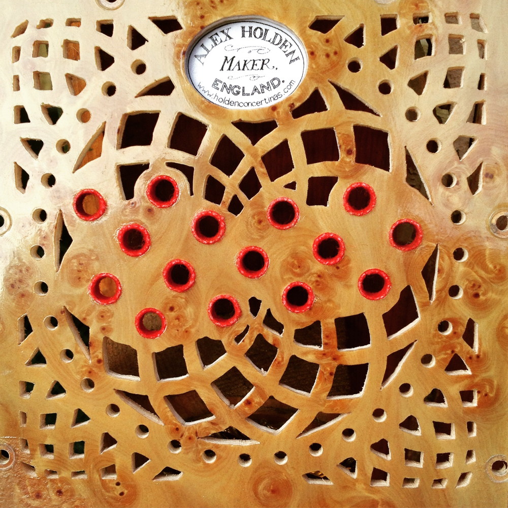
No. 1: Brun Part 3: End Boxes
Part 3 of the story of how I built my first instrument is going to cover the main wooden frames of the instrument ends; the bellows frames and the walls of the action boxes. I came up with what seemed like a clever plan on paper, but quite a few things went wrong along the way leading to a lot of fiddly corrective work and a couple of slight cosmetic issues in the finished instrument. The next instrument is definitely going to involve some significant changes in the way I build the end boxes.
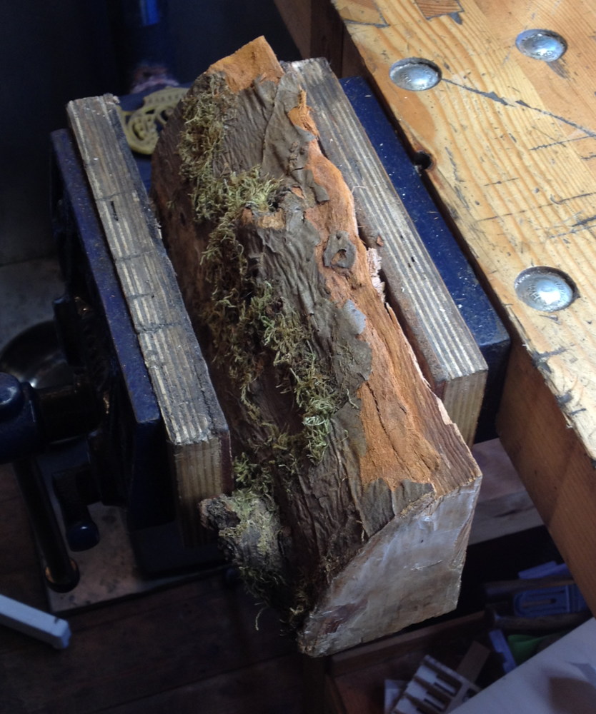
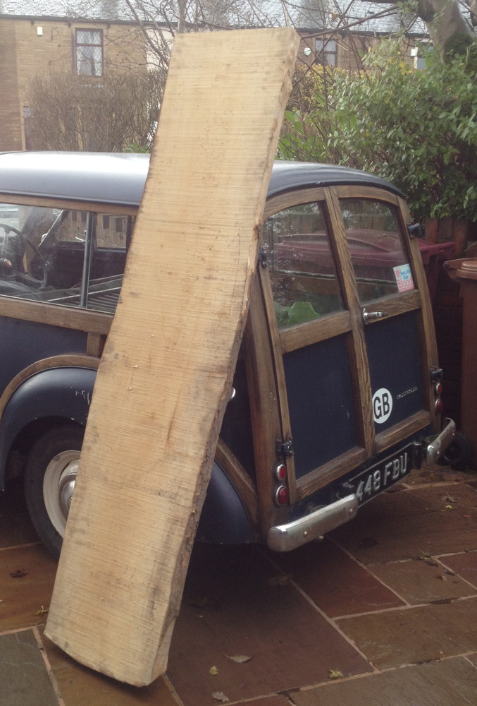
I had read that good quality vintage instruments were commonly built from sycamore, typically with decorative veneers like ebony or rosewood on the outside, though for this instrument I decided to go with plain solid sycamore and try to use nicely figured pieces of it for the most visible parts of the walls. I struggled to find a timber supplier that stocked quarter sawn sycamore, though after much searching I found a place thirty miles from me that had a stack of roughly 2 ¾” thick slabs that had been plain sawn and kiln dried. I went and searched through them and picked out one taken from the middle of the tree, so it had two quarter-sawn (ish) sections either side of the pith.
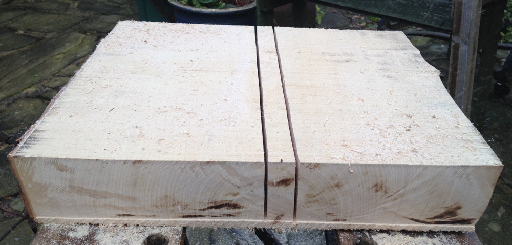
I used my circular saw to cut off a section and remove the pith (the centre of the trunk, where the growth rings become very small). If you click on the next picture to zoom in and look at the growth rings, you should be able to see what I mean. The areas where the rings meet the surface at a right angle are known as quarter sawn, and on sycamore they will show pretty figuring after planing it smooth.
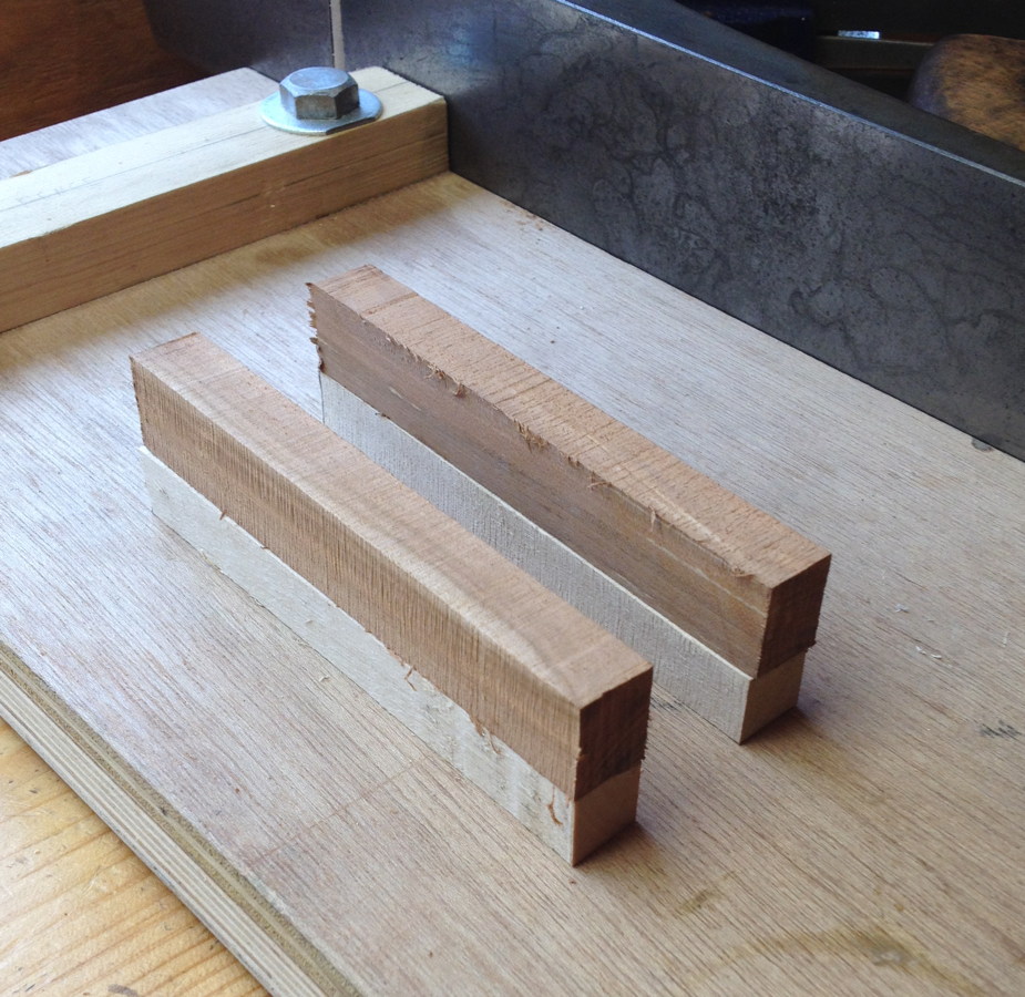
I next used my wimpy hobby-grade 9″ bandsaw to further break the chunks down into a set of thin boards approximately 3″ wide. It just barely succeeded, cutting very slowly with a great deal of groaning and stalling. I have since bought a much more powerful 12″ bandsaw that will make this sort of operation a breeze on future instruments.
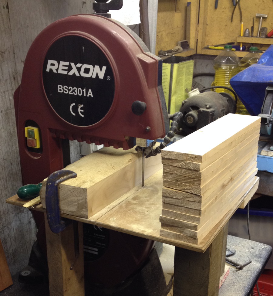
I cut more of them than I needed so that I had a selection from which to work around knots and pick the prettiest faces to be visible on the outside of the instrument. After ripping them on the bandsaw I stacked them with air gaps around them and let them acclimatise for a couple of weeks; this proved to be a good idea because they definitely warped a little in the first few days.
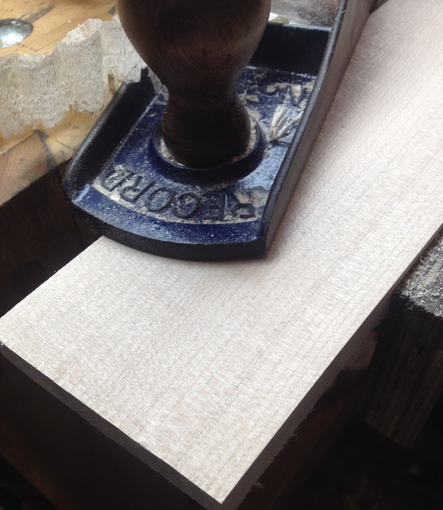
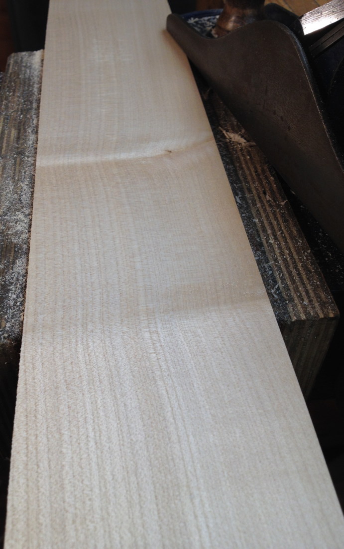
After drying I picked out the nicest ones and planed the best face flat, revealing the medullary ray flecks and occasional ripples:
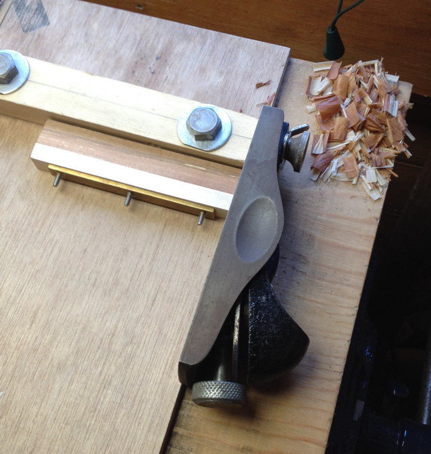
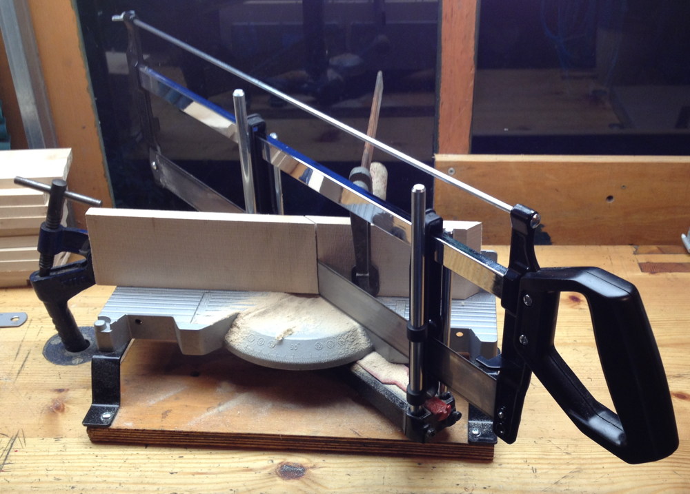
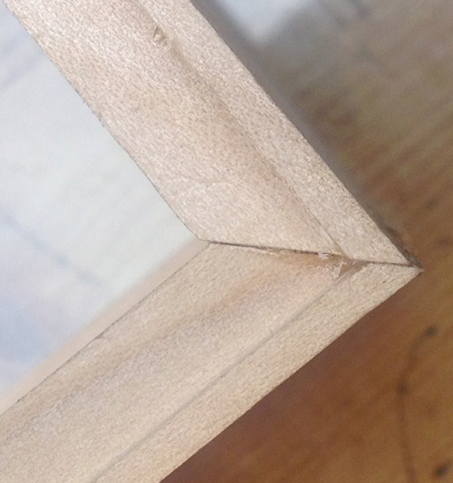
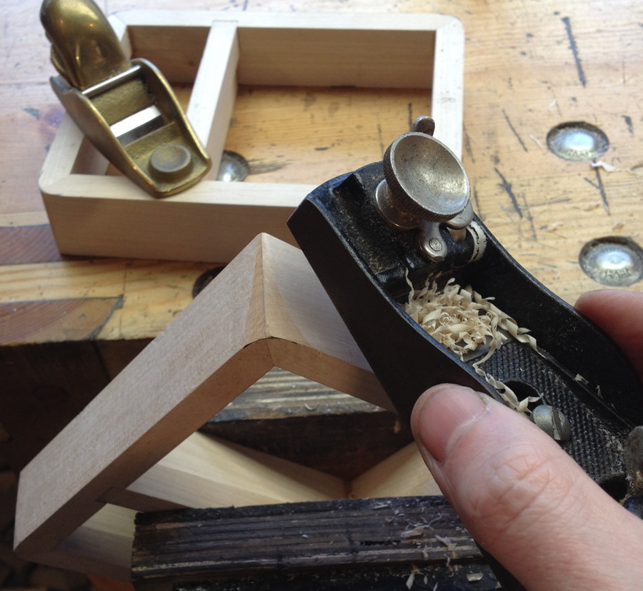
I mitred the ends, using the planed face as my reference:
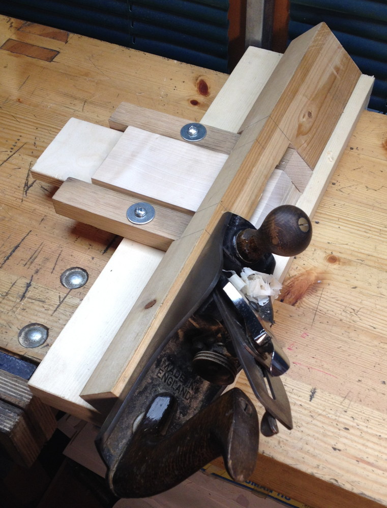
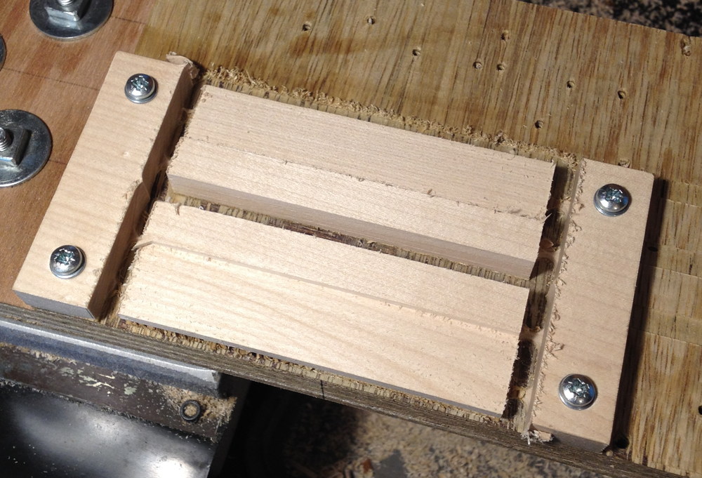
Then I cleaned up the mitres and trimmed them to exact length using a special 45° shooting board I made for the purpose:
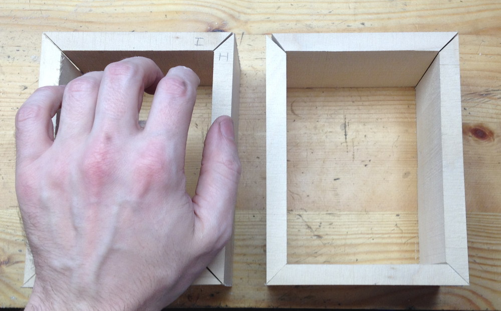
Trial assembly gave me my first real feel for how big this instrument was going to be relative to my hands:
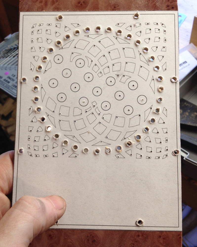
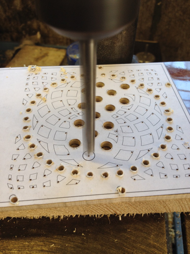
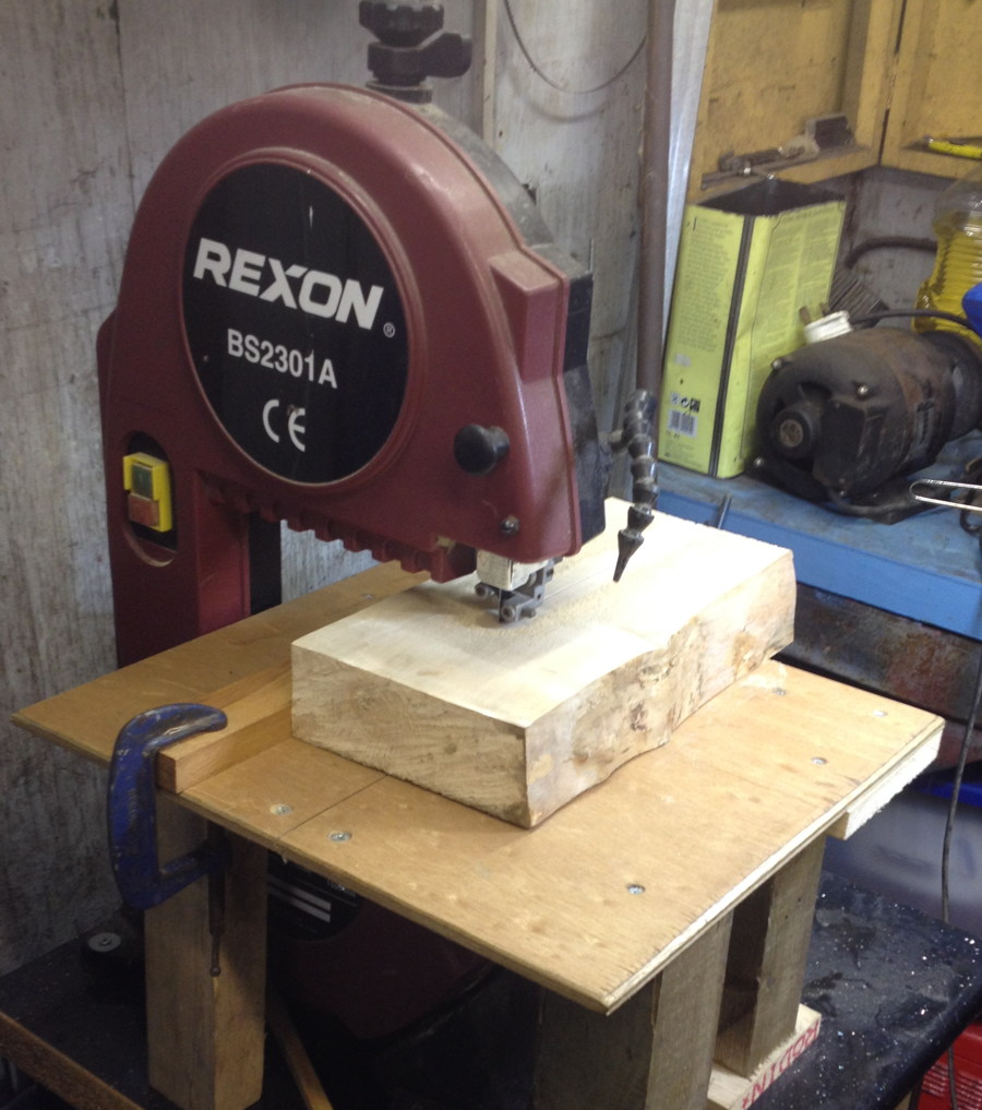
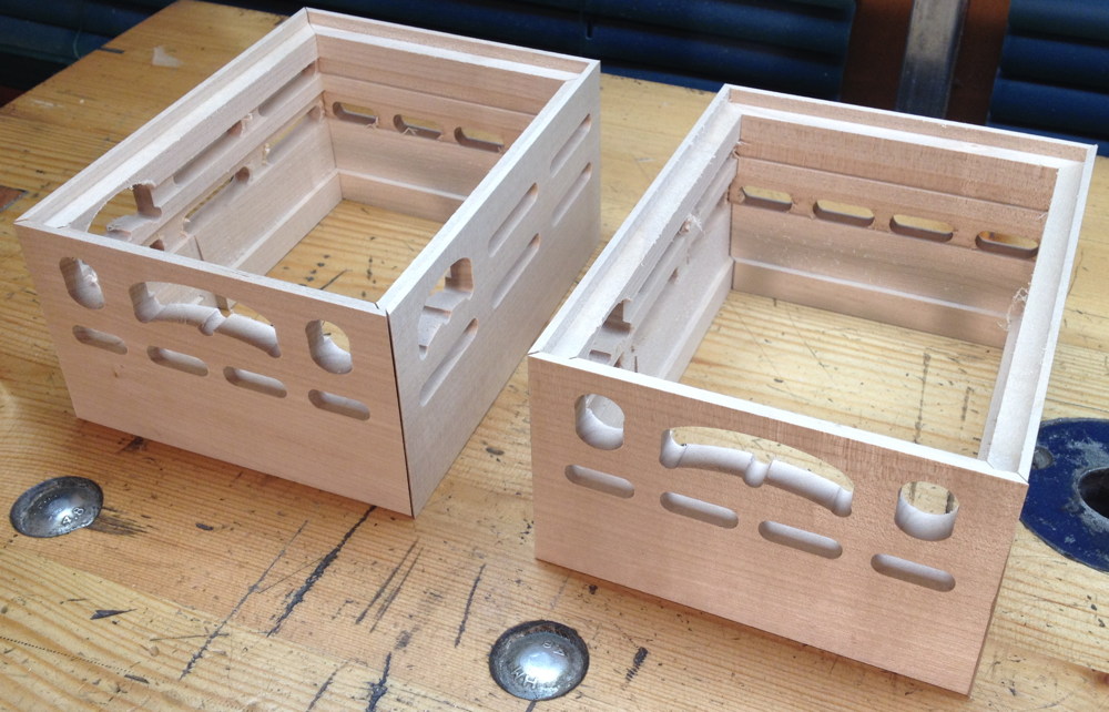
Here’s where my clever plan begins. I had the idea to cut various rebates and steps and sound holes and things, and even the tapered area of the bellows frame using the CNC mill, before gluing the boxes together. This part actually went fairly well, apart from me messing up the first one due to a programming error. The main problem was that it took quite a lot of work to do the CAD and CAM to program the machine (there were actually six different programs due to the differences between the sides: left left, left right, right left, right right, tops, and bottoms). You might also have noticed that I used sycamore for both the action boxes and the bellows frames: I’ve since learned that it is common to use a lighter, cheaper wood for the bellows frames; if I’d done that I could have still used the same technique by gluing a strip of sycamore and a strip of whatever secondary wood together before machining them as if it was a single piece.
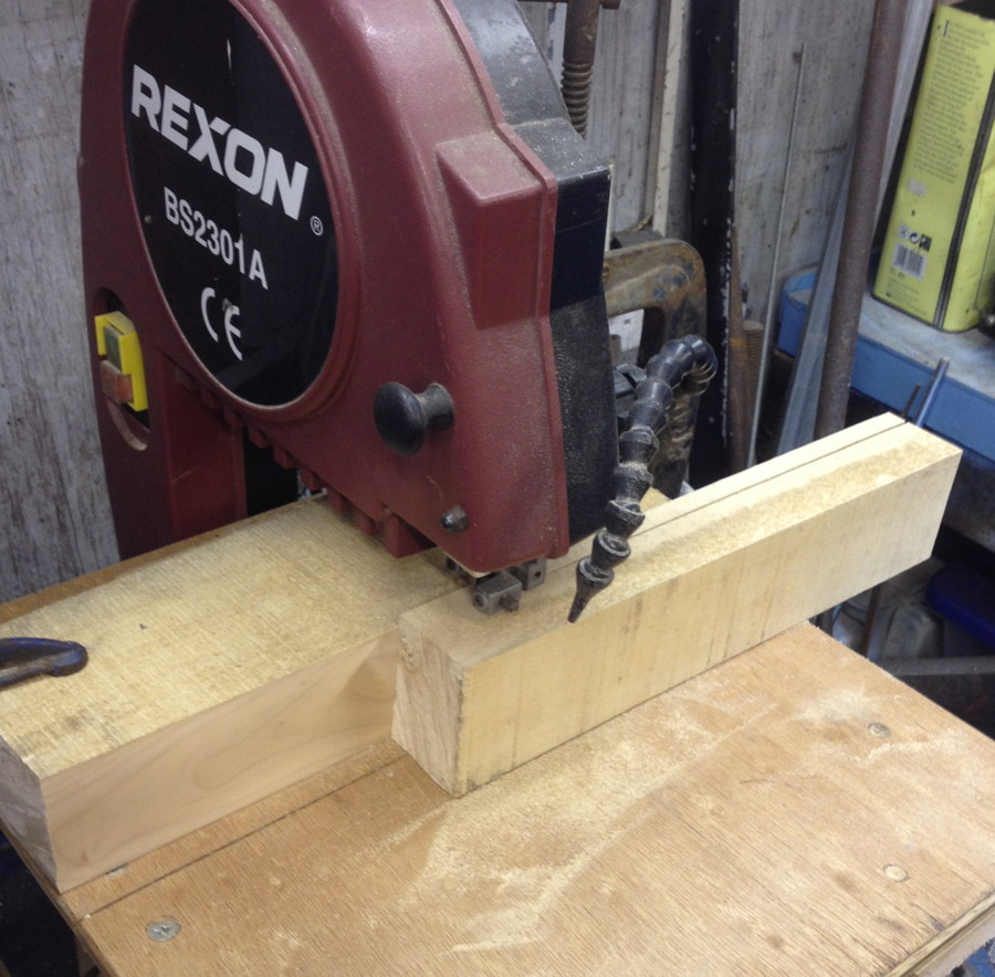
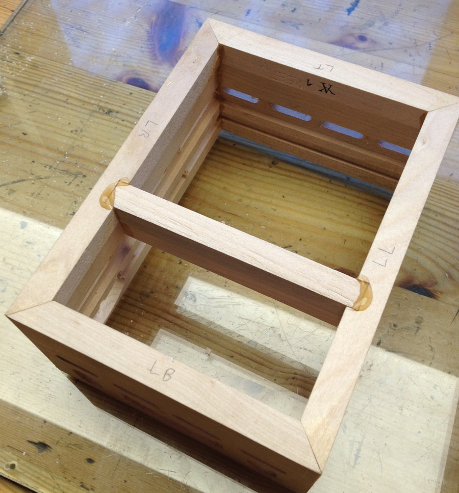
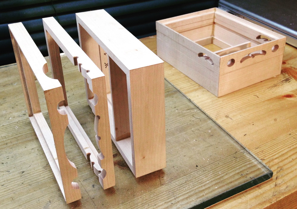
Trial assembly of all the sides before gluing:
Gluing. Here’s where things started to go wrong. The sides seemed to warp slightly when I put the glue on, making it extremely difficult to get them to line up perfectly. My first attempt was clearly a mess so I broke them apart before the glue had dried, washed the glue off, and tried again.
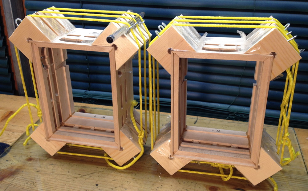
Second attempt didn’t look too bad at first:
But on closer examination, most of the joints were slightly squiffy, some more than others. It may not look like a lot, but it caused me all sorts of headaches further down the line.
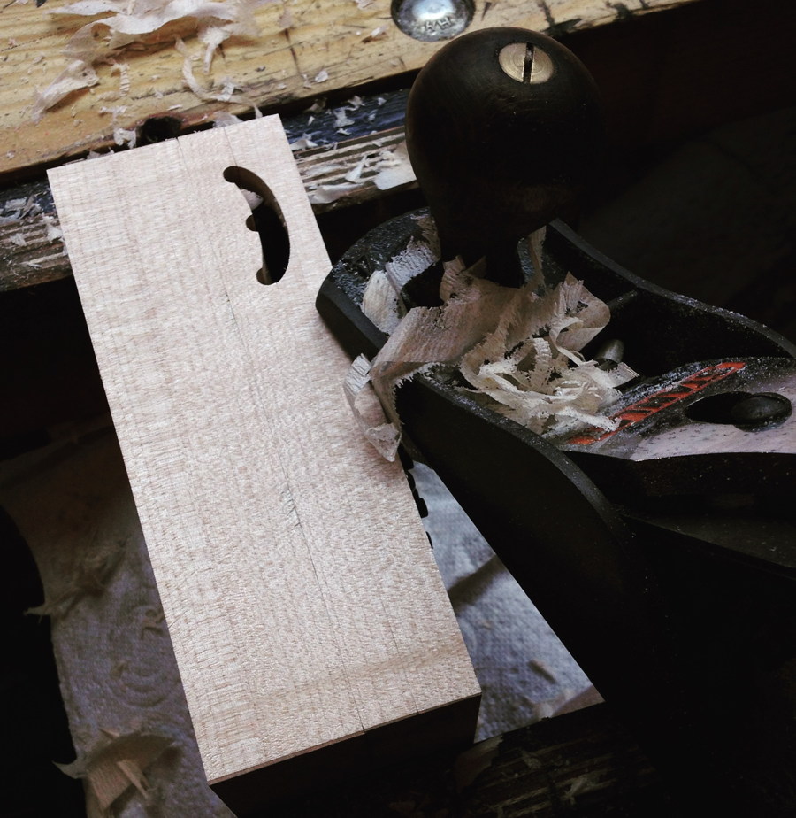
Unusually, the instrument has two reed pans per side. This meant I had to make a pair of dividing walls for the bellows frames:
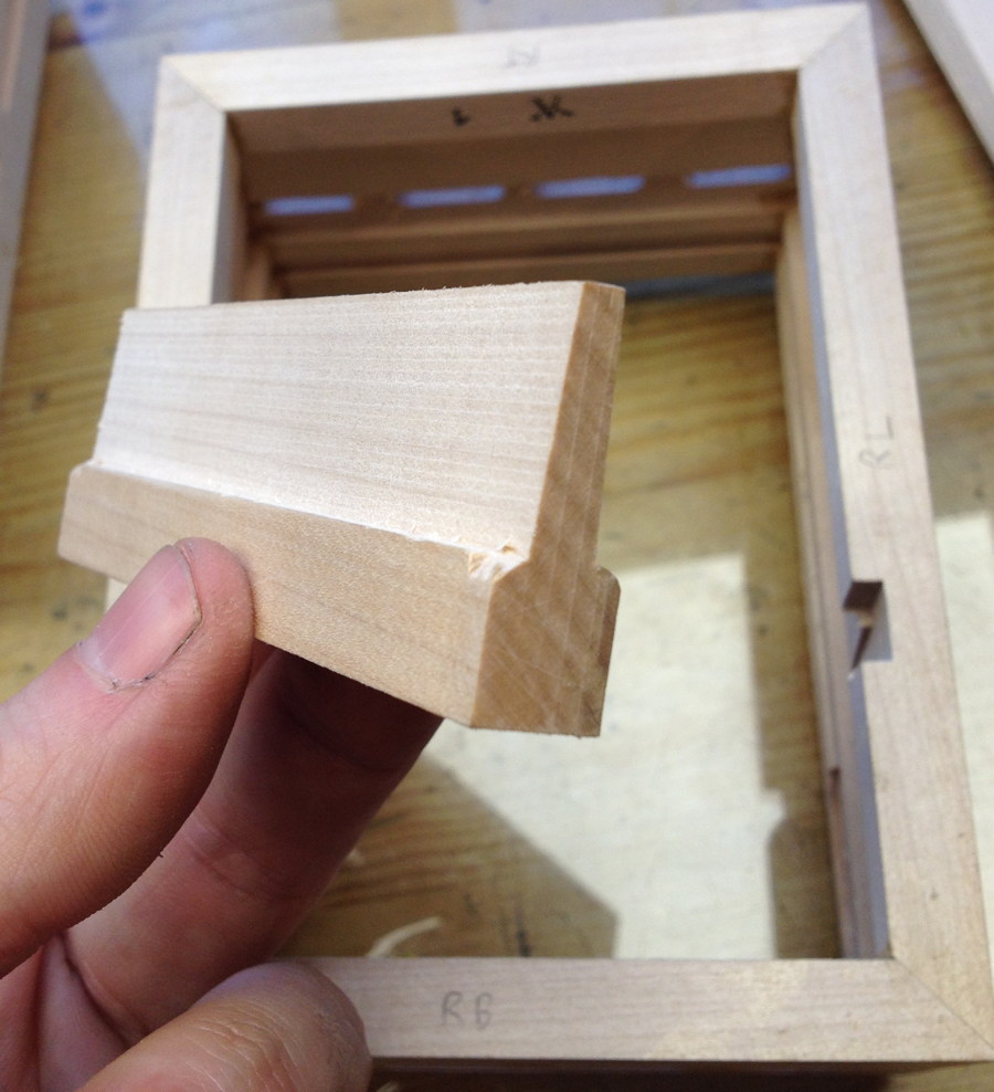
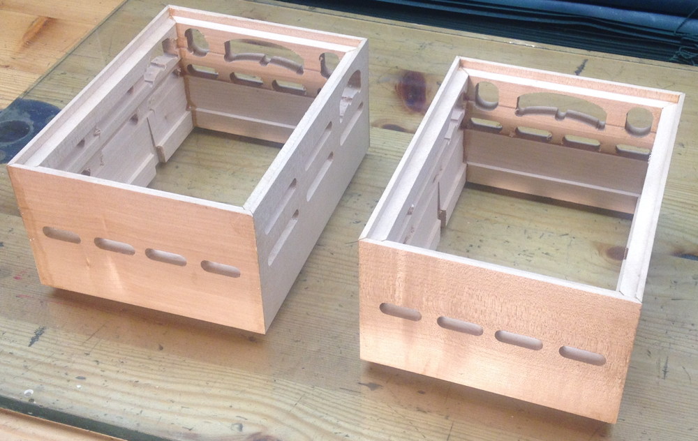
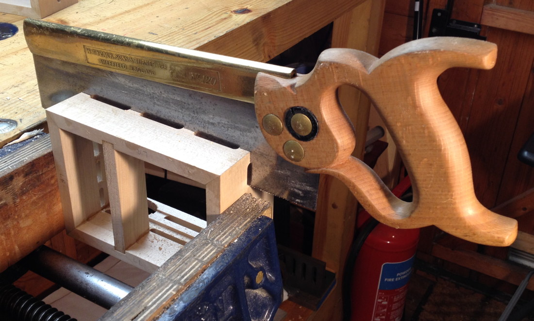
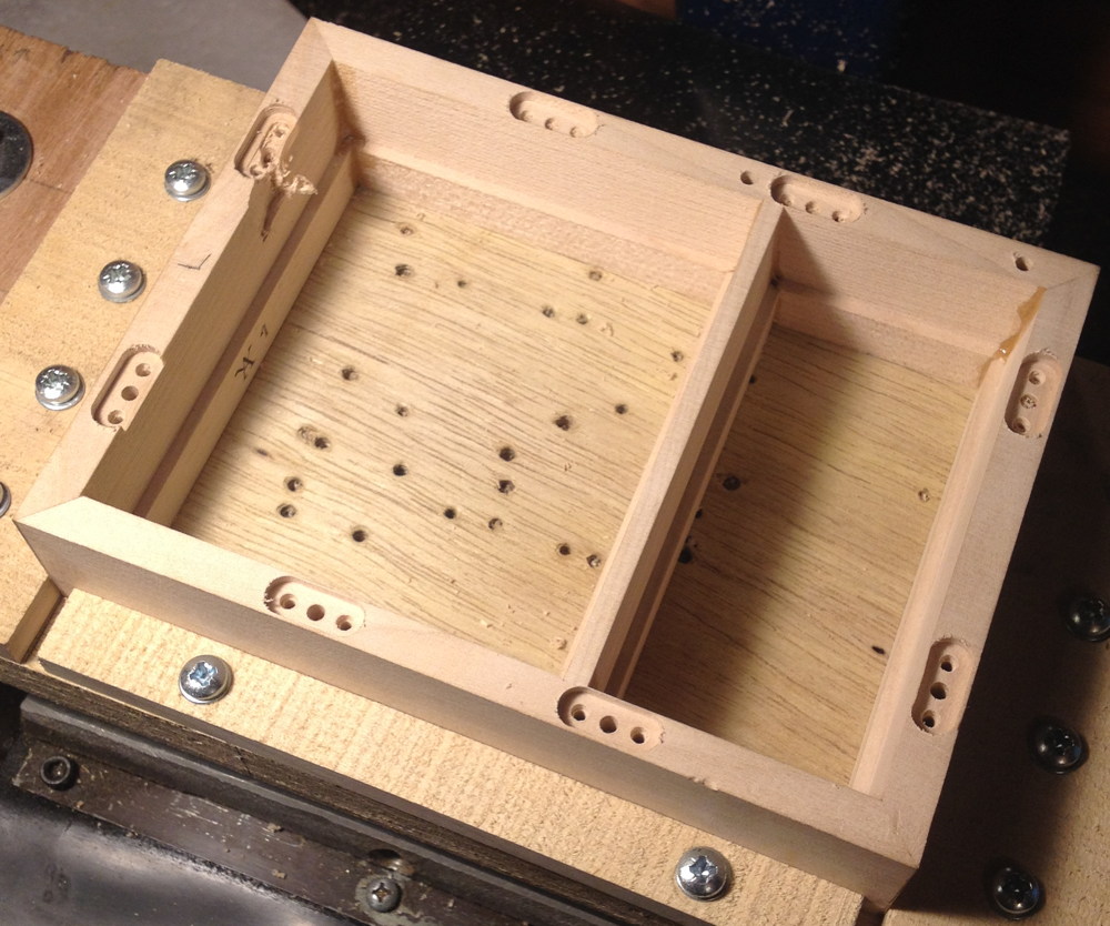
Next I cut the boxes apart into their three sections: the bellows frame and the two halves of the action box. I was a little nervous about this step but it went smoothly. Those slots routed in the walls are there specifically to make it easier to cut the boxes apart.
Incidentally, I didn’t know at this stage how deep the reed pans were going to be so I made the bellows frames fairly deep to be on the safe side. They probably could have been 5mm shallower in hindsight. This caused me a bit of a headache later on because I ended up having to accurately shim the bottom of the reed pan recesses on both sides because they were both deeper than the reed pans I actually made.
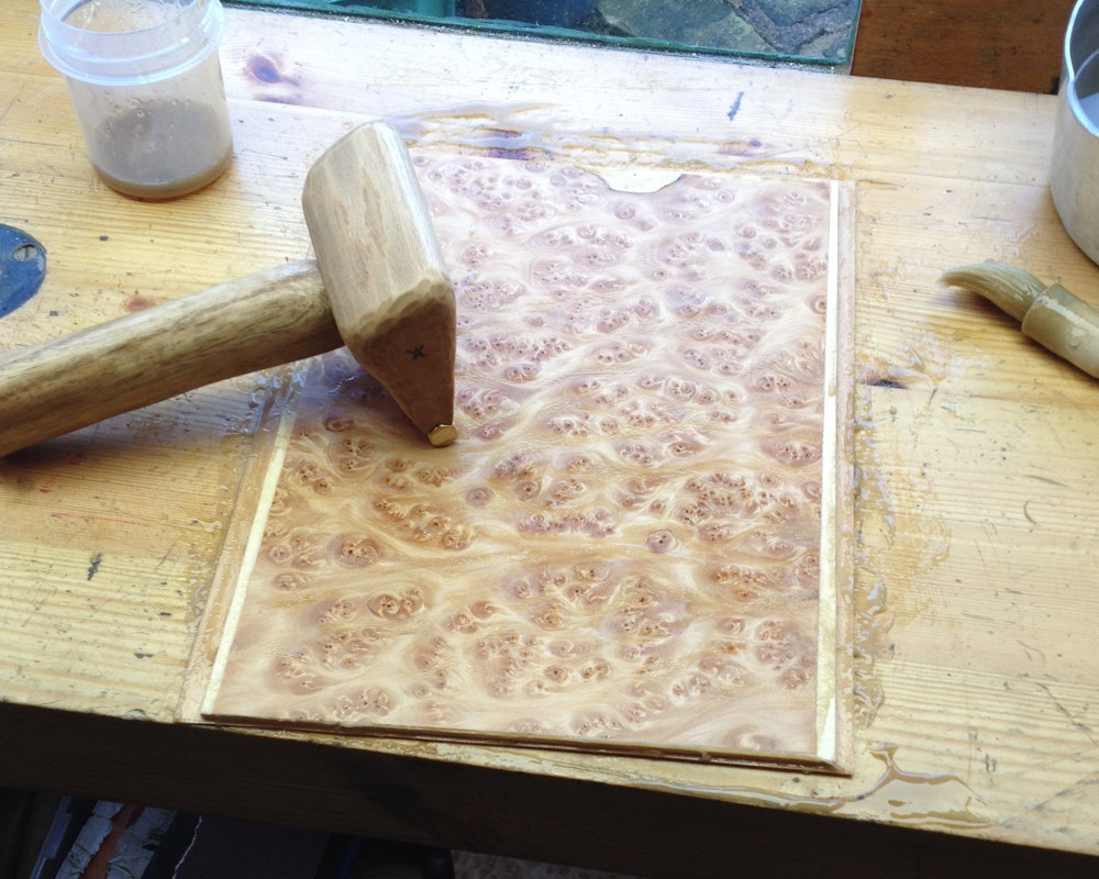
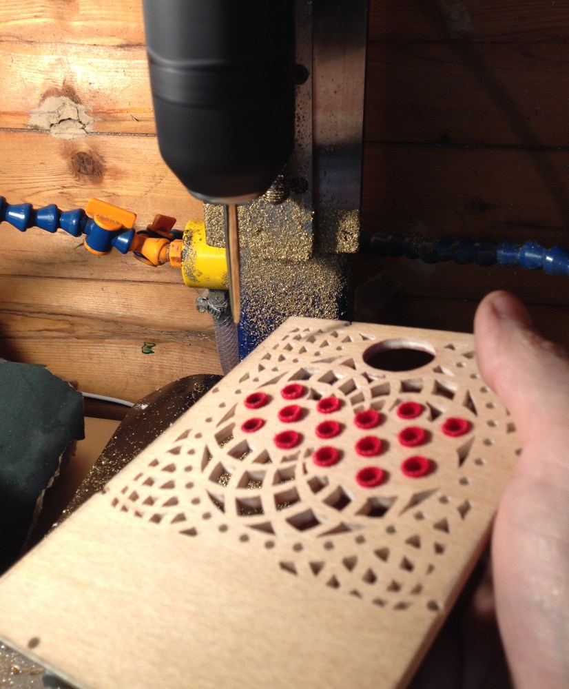
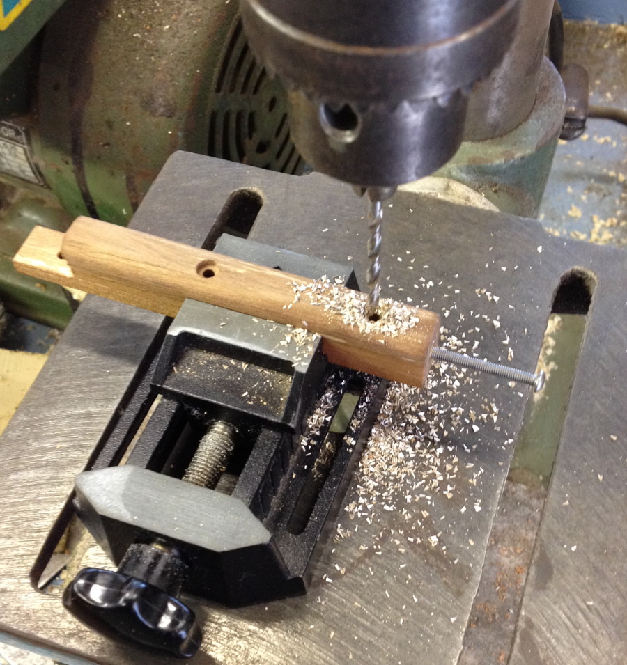
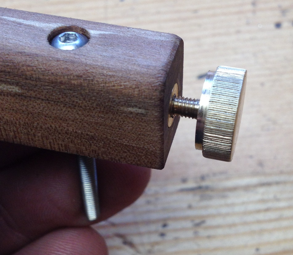
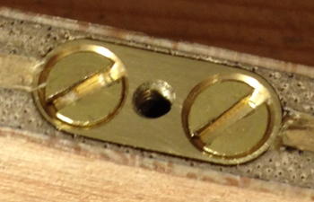
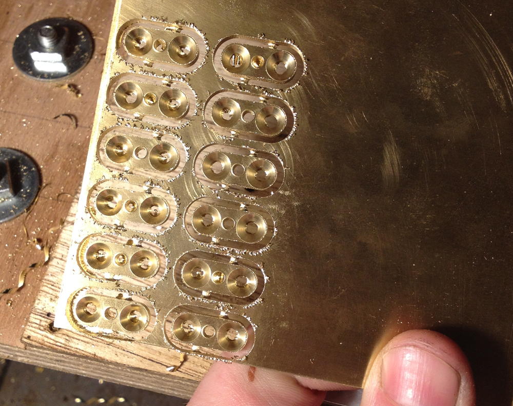
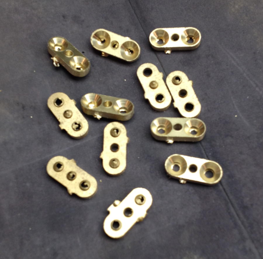
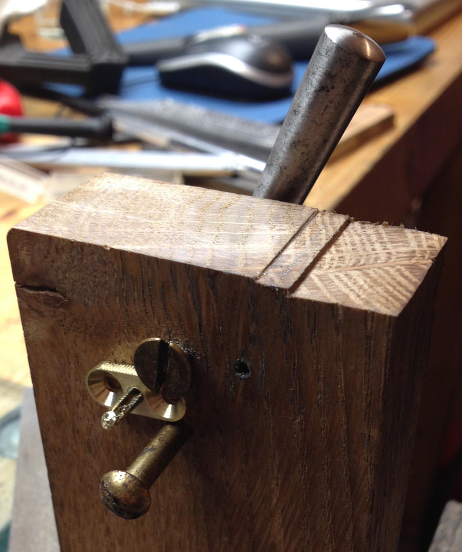
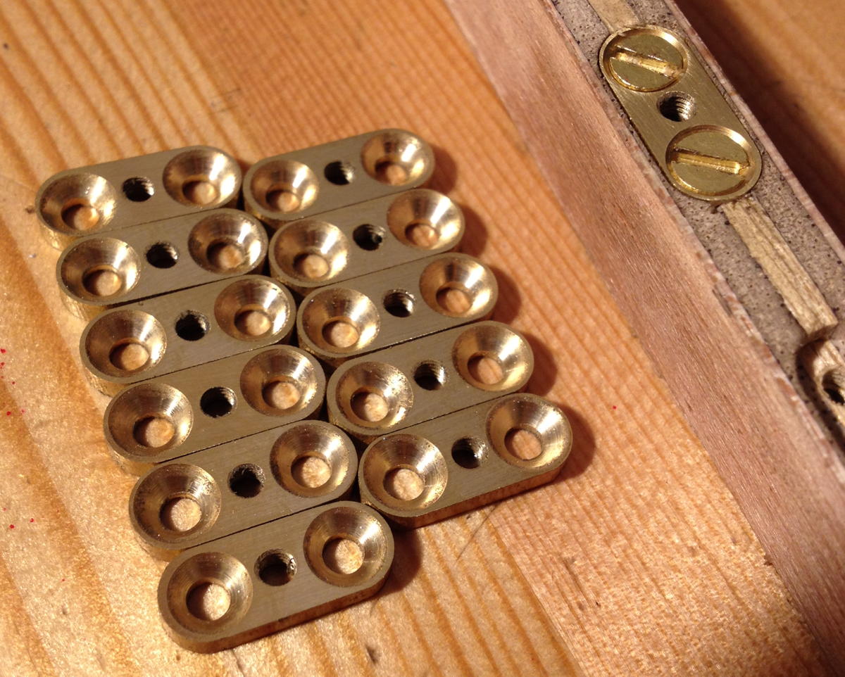
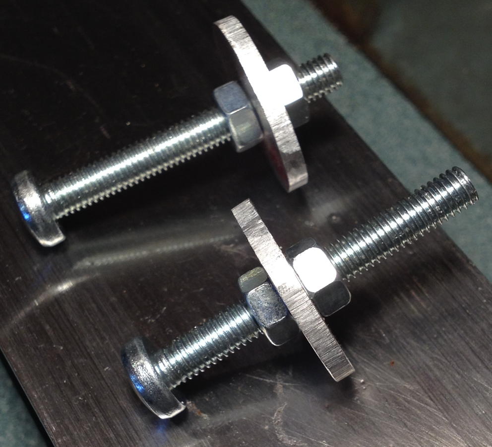
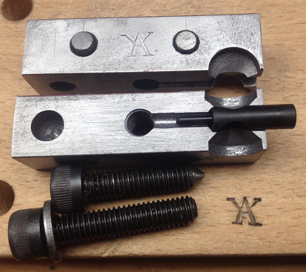
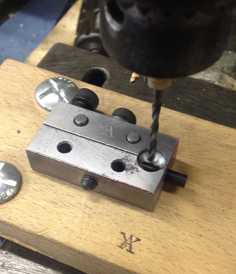
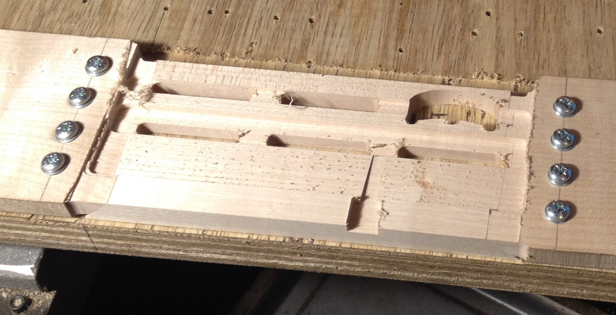
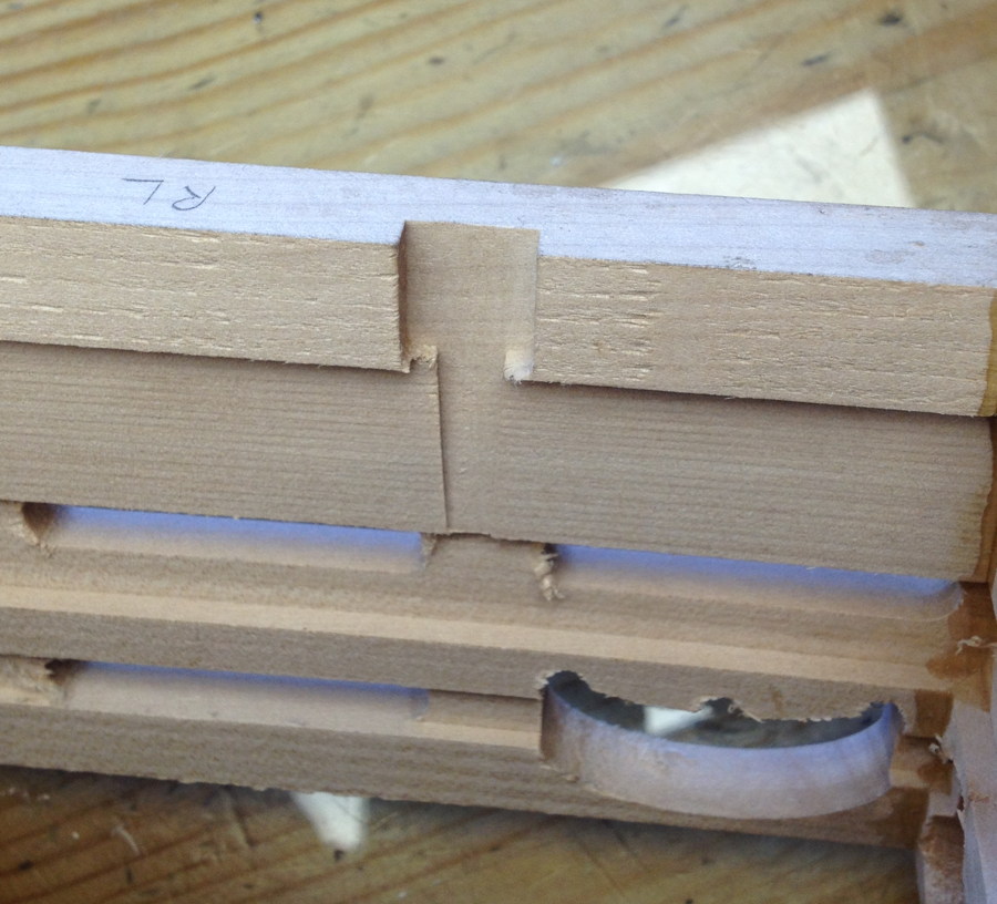
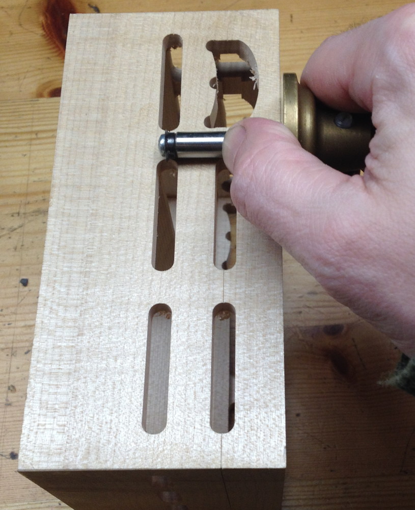
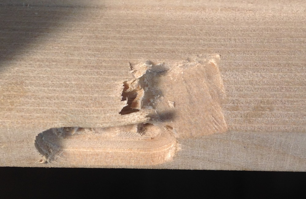
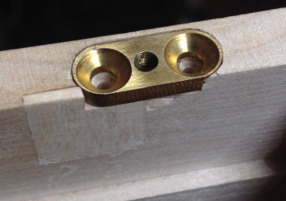
Next I had to inlay the captive nut plates in the bellows frames, and drill the bolt holes in the action boxes. All sorts of things went wrong during these operations, some of them because the frames weren’t perfectly square, some because my milling machine wasn’t big enough to get to all of the walls without turning the boxes 180 degrees. I’ll definitely be working on coming up with an easier and more reliable way to do this operation for the next instrument. The worst thing that went wrong was one of the bellows frames came loose from the (inadequate) clamps and the router bit tore a chunk out of the inside of the wall.
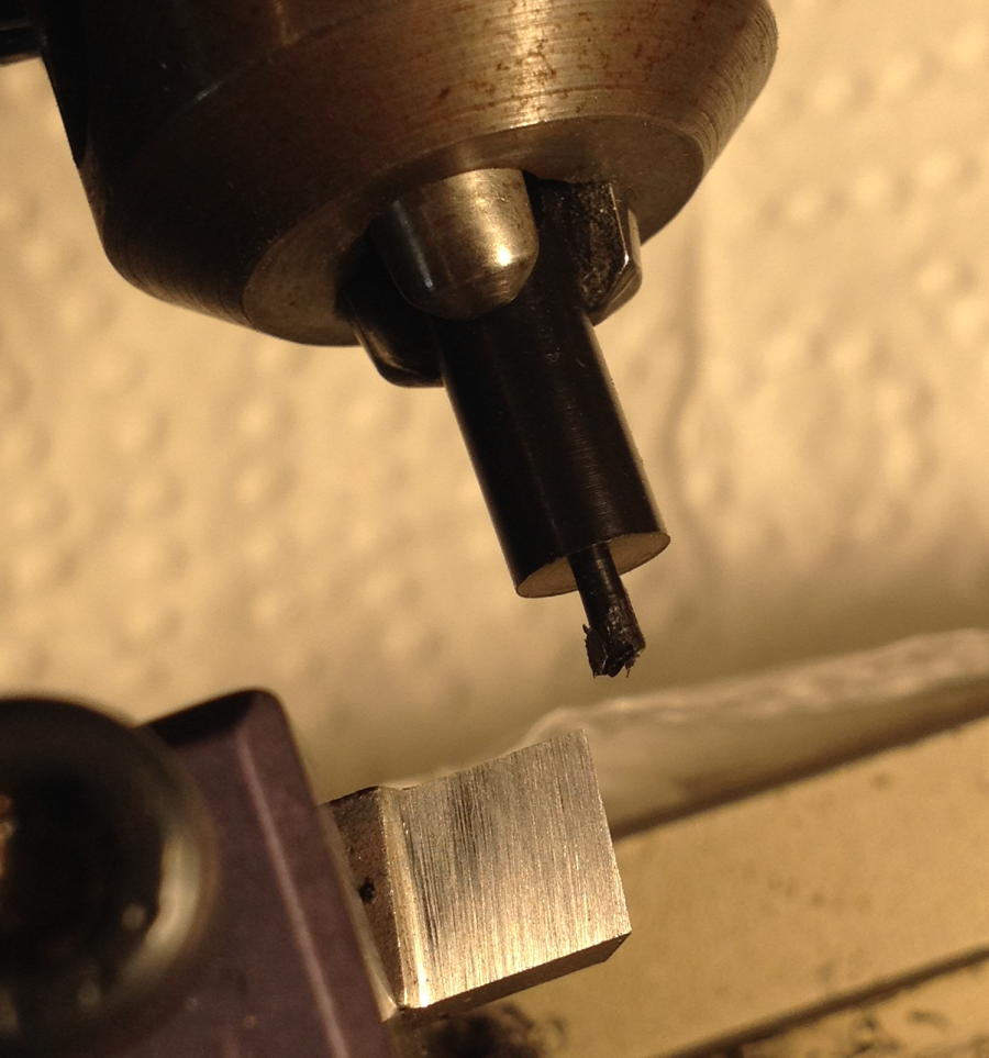
I had my finger on the emergency stop button and managed to hit it before it had done too much damage:
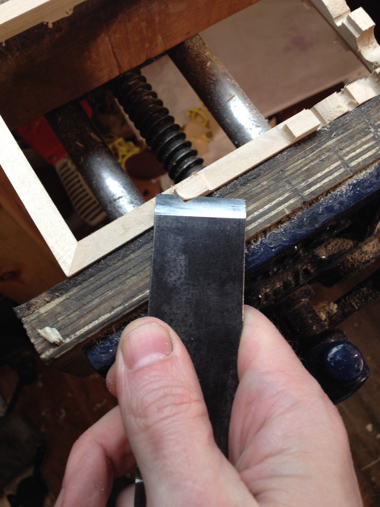
I repaired it by cutting a section out, gluing in a new piece, and planing it flush:
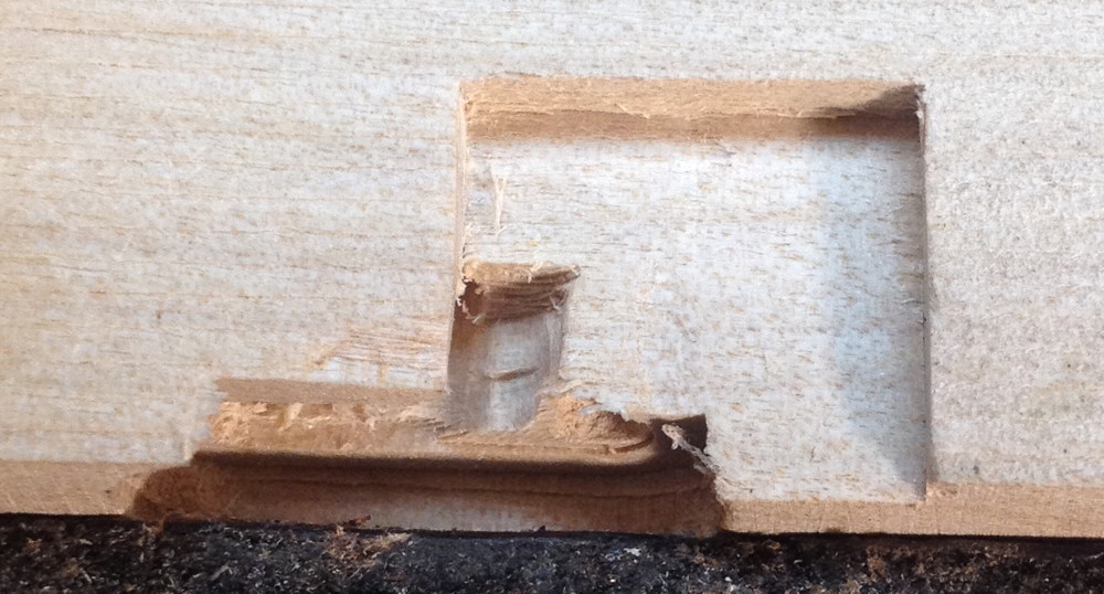
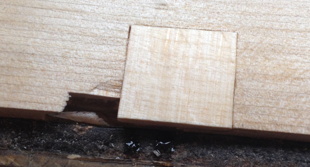
The repair is hidden on the inside of the instrument, underneath the chamois leather gasket.
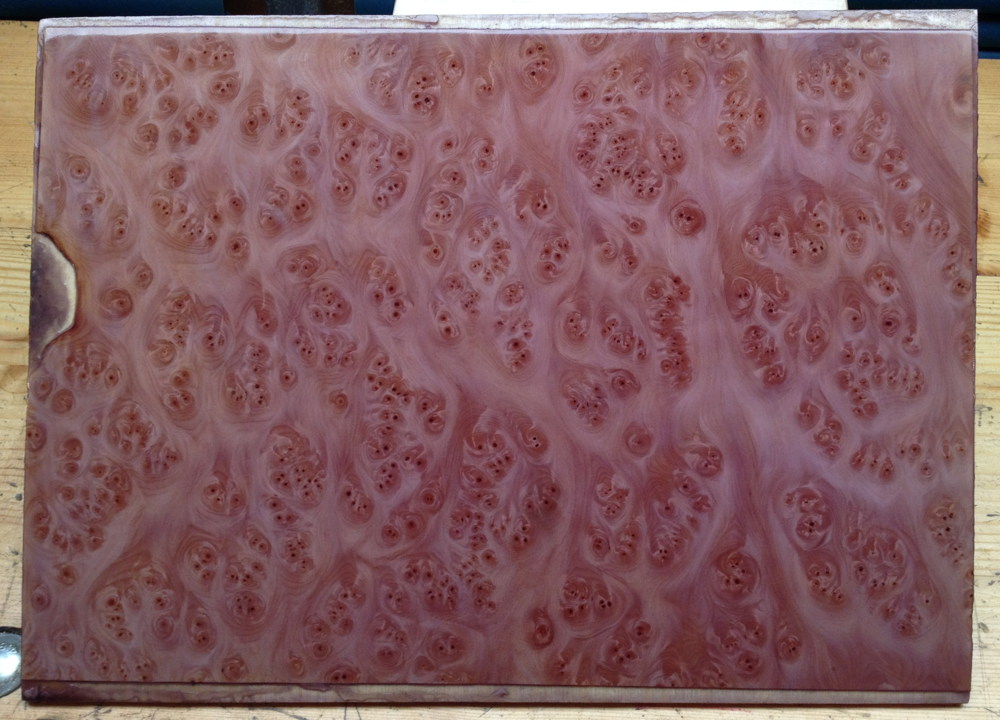
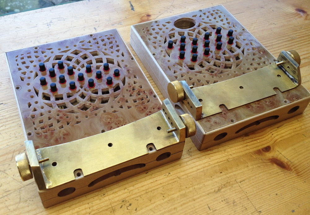
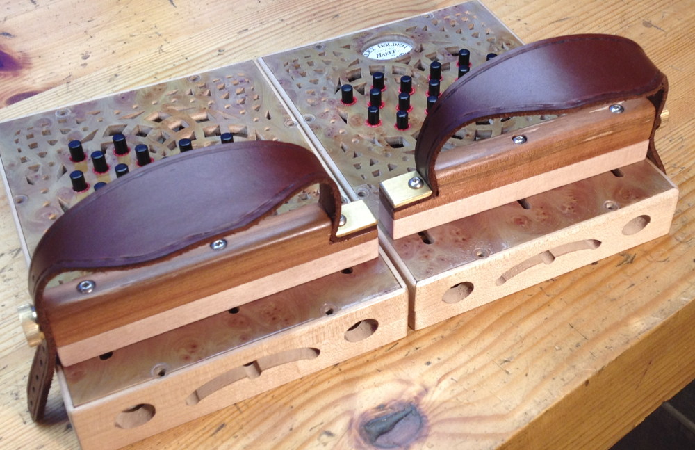
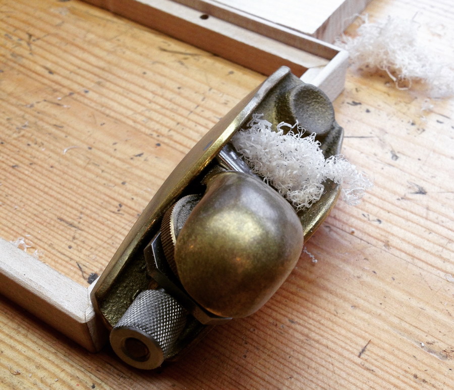
With the nuts installed, I was able to bolt the boxes together and lightly plane the outsides to get the walls to match up nicely (zoom in to see the nice figuring):
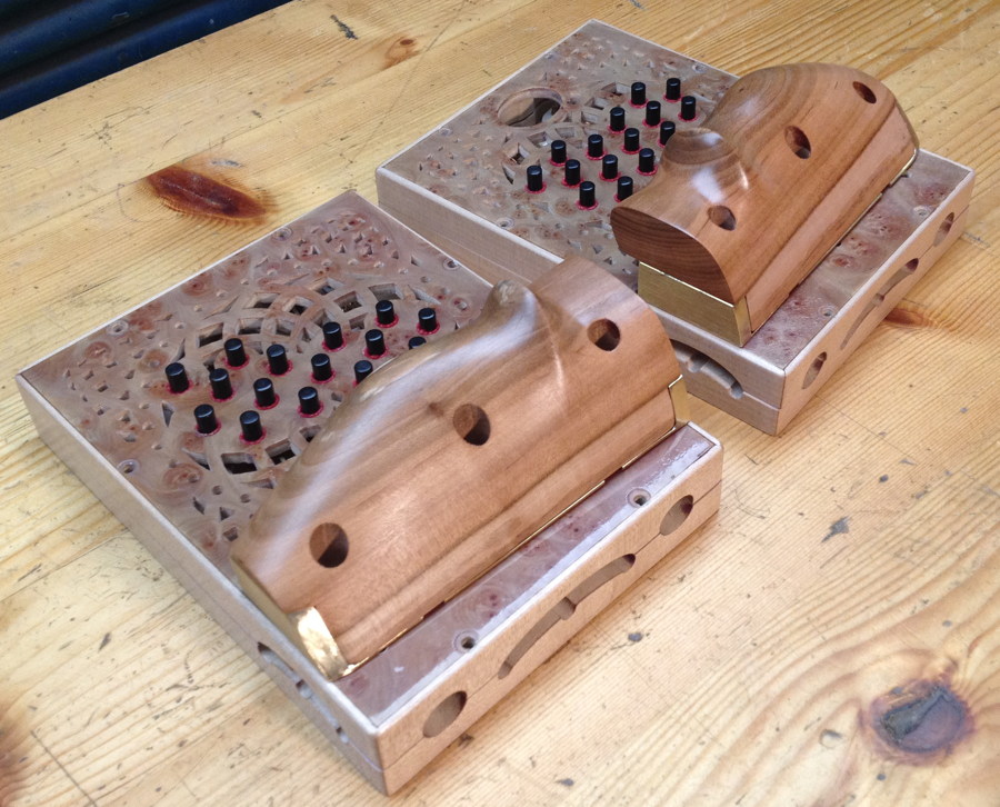
I slightly rounded all the corners so it feels comfortable to hold:
The outside of the bellows frame needed planing to taper it down slightly and round the corners where it meets the bellows, which are deliberately slightly smaller than the boxes and have rounded corners.
I then lightly French-polished the action boxes, leaving the bellows frames bare because I needed to glue the linen and leather to them. After all the difficulties I had polishing the end plates, I was starting to get the hang of the technique by this point and did a much more satisfactory job of polishing the action box sides. If you zoom in you can see how it really brought out the figure of the wood. The dye in the meths still made the finish look a little bit purple, though!

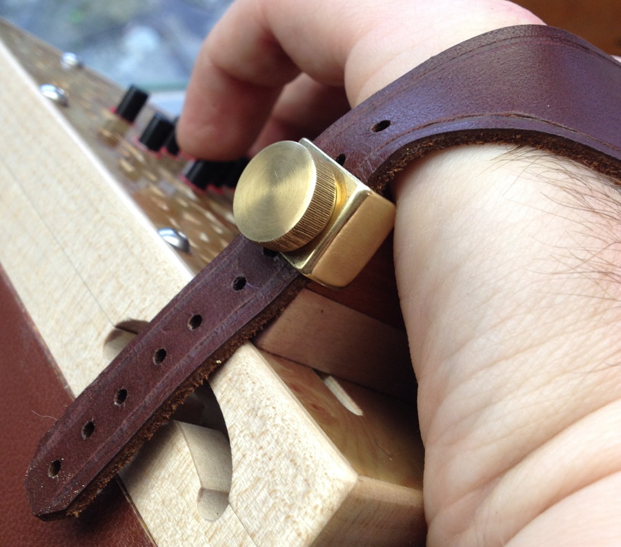
I made a rookie mistake at this stage: as you can see in the previous photo, the bellows frame walls perfectly meet the action box walls with no step. What I should have done was to plane the action boxes a tiny bit smaller, so that when I glued the leather on, the leather would have been able to come right up to the underside of the action box without the edge being visible. I tried to work around the problem by skiving the leather down to virtually nothing where the frame ends, but it didn’t work perfectly and the join between the two looks slightly crude. It probably also would have helped if I’d made the end run a couple of mm wider and wrapped the skived edge of the leather around the corner a little, so the edge of the leather end run was clamped inside the joint between the boxes, underneath the chamois gasket.
No. 1: Brun Part 3: End Boxes Read More »